12
instructions for installation
ELECTRICAL CONNECTIONS
S200
BEFORE MAKING THE ELECTRICAL CONNECTION OF THE AUTOMATION, CHECK THAT:
•
The main power supply connected to the automation must comply with the requisites contemplated by the legislation in force in
the country of installation, and must have the technical characteristics indicated in tab.2- cap.2.5 and on the rating plate, as well
as the “CE” seal of approval.
•
Electrical connection of the automation must be made exclusively by skilled, qualified technical personnel in possession of the
professional requisites contemplated by the legislation in force in the country of installation, who shall issue the client a declaration
of conformity of the connection and/or installation made.
•
The main power supply connected to the automation shall be provided with an omnipolar magneto-thermal differential 30ma switch
with aperture of at least 3 mm between the contacts. This device shall be installed in the power supply system in accordance with
the requisites contemplated in the legislation in force in the country of installation.
•
The power line must be protected against earth leakage and the installation shall provide a grounding line longer than the power
line so that if pulled, the ground line is the last to go taut.
•
Before making electrical connections make sure there is no power on the mains.
•
The recommended power cables are as follows: H05VV-F 3X0.75, H05RN-F 3X0.75, self-extinguishing types for electrical con
-
nections. For wiring of the analogue selector we recommend using a multipole 8 x 0.5 type LI-YY.
•
The installer shall take care to secure the power cable stably inside the automation. The cable will be inserted in the main entry
hole of the automation with its sheath.
•
Limit stripping of the primary sheath of the cable to the distance necessary for connection to the terminal
•
Before making the electrical connection of the automation, check that the power cable is undamaged.
•
The hole in the substratum for passage of the power cable shall be made without rough or sharp edges or points that could dam-
age the cable.
•
In addition to the standard holes for cable entry, the side covers are predisposed to create another holes for cable entry.
•
Connection to the power mains in the portion outside the automation shall be made on an independent channel, separate from the
connections to the control and safety devices.
•
Any type of electrical material (plug, cable, clamps, etc.) used for connection must be suitable for the purpose, marked “CE” and
must comply with the requisites envisaged by the legislation in force in the country of installation. For wiring, use cable with double
insulation up to the immediate vicinity of the connectors.
•
Whenever the operator is powered up with battery only, and whatever is the operation mode set, to perform a complete
power off, press and hold for 5 seconds near/reset button.
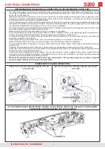
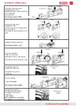
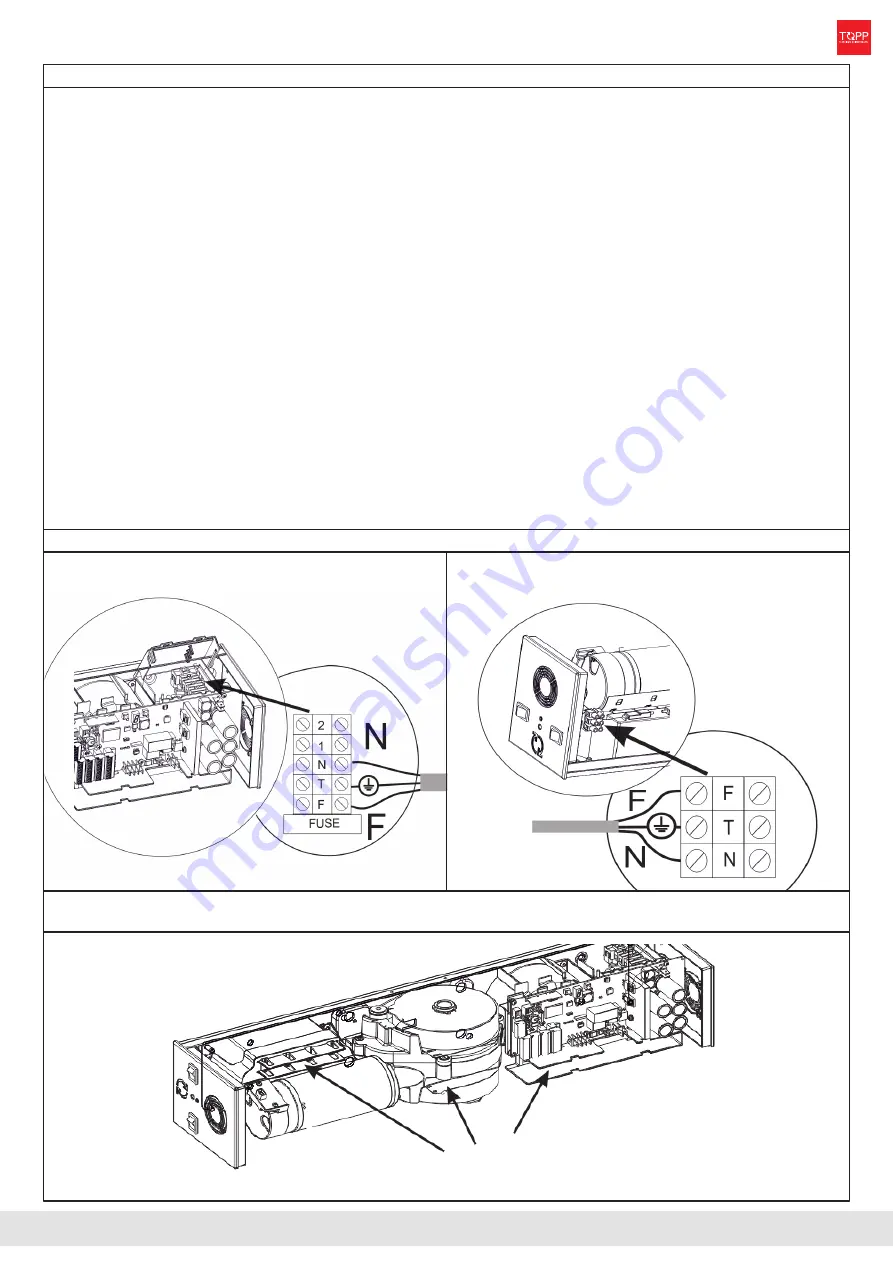
POWER SUPPLY CABLES CONNECTION
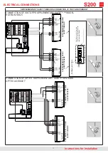
ENTRY OF ELECTRIC POWER CABLES ON THE
BOARD SIDE:
ENTRY OF ELECTRIC POWER CABLES ON THE MO-
TOR SIDE:
IF THE POWER CABLES ENTER FROM THE SIDE OF THE MOTOR, DRIVE THE AUXILIARY CABLES INSIDE
THE GROOVES/CHANNELS MADE FOR THIS PURPOSE
CHANNELS
Summary of Contents for S200
Page 20: ...20 instructions for installation LIST OF ERROR MESSAGES AND NOTICES S200 ...
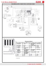
Page 26: ...26 instructions for installation PRE WIRED ELECTRIC CONNECTIONS S200 ...
Page 30: ...30 EC DECLARATION OF CONFORMITY instructions for installation S200 ...


