background image

29

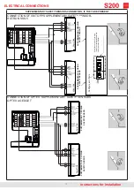
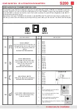
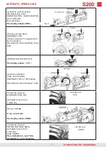
SERVOASSISTED FUNCTION WITH DISABLE USER BUTTON

By connecting the external and internal opening buttons as per the following diagram and correctly setting parameter 

113 on the board, the door will enter Servo / Push & GO mode. Setting parameter 113 = 3, the Push & GO function is 

activated with safety sensors activated Setting parameter 113 = 2 the Push & GO function is activated with sensors 

deactivated it is necessary to activate the LOW ENERGY.

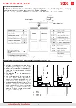
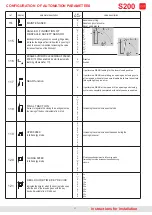
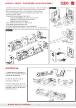
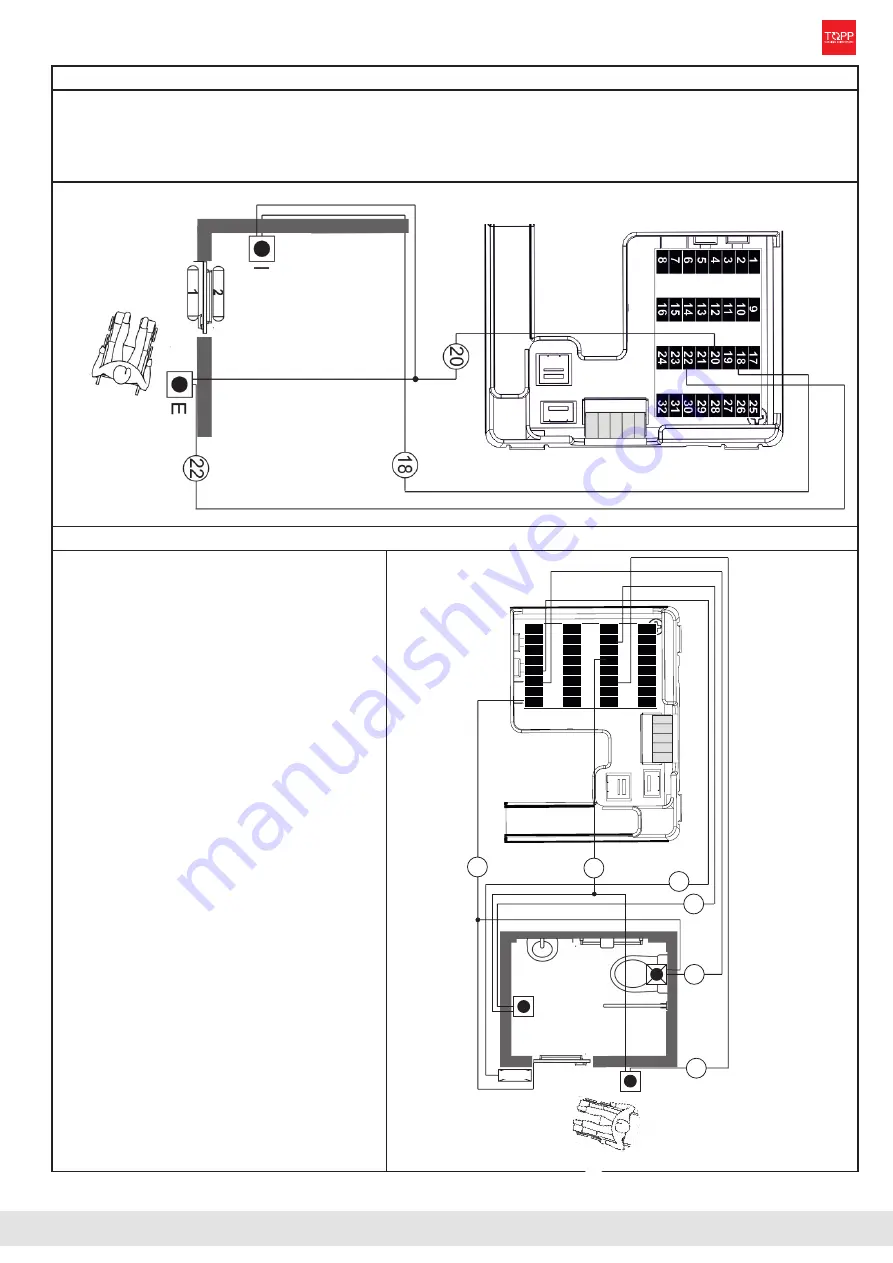
DISABLED USER RESTROOM DOOR FUNCTION (parameter 135  =9)

The system functions sequentially:

• 

When the restroom is free, pressing the ex

-

ternal button opens the door. 

•  If the door is closed pressing the internal 

button closes the door and locks it with the 

electric  lock,  signaling  that  the  restroom  is 

occupied.  

•  Pressing the internal button opens the door if 

the door is not closed. 

• 

The  door  is  equipped  with  an  electric  lock 

connected  to  the  input  board.(see  pag.16)

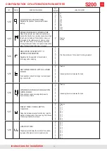
The external radar input (22 ) should be con

-

nected to a button on the outside of the re-

stroom. 

• 

The  internal  radar  board  input  (18  )  will  be 

connected to a button on the inside of the re-

stroom.

• 

On the output of the air curtain  (6 ) a flush 

command can be installed. 

•  The output on the disabled user restroom 

display    (5)  is  connected  to  a  display  that 

shows “occupied” or “free”.

• 

Set a time parmeter 122 sufficiently long to 

allow a disabled user to enter the restroom.

• 

Set the parmeter 104 = 0

DISABLE SPECIAL FUNCTIONS

instructions for installation 

S200

1            9           17          2

5

6           14          22          3

0

2           10          18          26

3           11

          19          2

7

8           16          24          3

2

7           15          23          31

4           12          20          2

8

5           13          21          2

9

occupato

5

6

18

22

E

I

8

20

Summary of Contents for S200

Page 1: ...1 INSTRUCTIONS FOR INSTALLATION AND USE S200 STANDARD INSTALLATION ORIGINAL INSTRUCTION COD 0P5701 VER 00 REV 03 20 instructions for installation ...

Page 2: ...nd SAFETY PAG 4 PRELIMINARY OPERATIONS PAG 5 ARTICULATED ARM INSTALLATION PAG 6 SLIDING ARM INSTALLATION PAG 8 SLIDING ELBOW ARM INSTALLATION PAG 10 ELECTRICAL CONNECTIONS PAG 12 FIRST STARTUP SELF LEARNING PAG 17 DOUBLE LEAF INSTALLATION PAG 18 MESSAGE LIST ERRORS PAG 20 21 ENTER DOWN ...

Page 3: ...ith sliding or elbow arm and in the push outward configura tion with normal arm The symmetrical feature of the automation facilitates the installation process The opening and closing movement of the door is regulated by the software of the electronic circuit board which manages the application of the forces and the continuity of movement in the different configurations The electronic board is a mi...

Page 4: ...e of user is low INSTALLER Installation of the automation must be made exclusively by qualified technical personnel in possession of the professional requisites contemplated by the legisla tion in force in the country of installation Theinstallermustbeabletoinstalltheautomationandstartit andtooperateinthepresenceofelectricalpowerinsideelectriccabinetsandshuntboxes Hemust be qualified to make all t...

Page 5: ... ARTICULATED ARM AND DOOR WIDTH BELOW 800mm 3 REDUCE THE SPRING TENSION a Loosen the grub screw in the electronic board side GLS to trigger the anticlockwise rotation of the spring b Screw back GLS c Loosen the grub screw in the motor side GLM to trigger the anti clockwise rotation of the spring d Screw back GLM e Repeat points a and b SENSORS POSITION instructions for installation PRELIMINARY OPE...

Page 6: ...lower end of the frame The automation must be fixed on the opposite side of the hinge The distance A varies according to the type of the Axle extension used see table COMPONENTS 1 Cover triangular plates and 6 fixing screws 2 Automation S200 3 Fixing plate 4 Automation fitting nuts 5 Articulated arm 6 Axle extension and corresponding screw optional Supplied separately Automation positioning with l...

Page 7: ...e motor axis Before installation see the Additional instructions ARM ADJUSTMENT 1 Fasten the arm bracket with two appropriate screws in the points previously pre drilled and loosen the two screws for the arm length adjust ment 2 Make sure the door is closed position the extend able lever of the arm at a 90 angle from the door adjust the arm length and tighten the two adjust ment screws ARM FITTING...

Page 8: ...tension used see table fixing plate Door edge fixing plate Door edge COMPONENTS 1 Cover triangular plates and 6 fixing screws 2 Automation S200 3 Fixing plate 4 Automation fitting nuts 5 Sliding arm 6 Axle extension and corresponding screw optional Supplied separately Automation positioning with left hinge Attention to the arrow on the fixing plate the door edge and the axis of rotation of the doo...

Page 9: ...the two larger holes on the outside Before installation see the Additional instructions SLIDING GUIDE FITTING 1 Make sure the door is closed and fasten the sliding guide with two appropriate screws in the points previ ously pre drilled 2 Fit the caps in the front holes 3 Fit the lateral caps of the guide ARM FITTING 1 Make sure the door is closed 2 Apply the supplied glue to the upper part on the ...

Page 10: ... A varies according to the type of the Axle exten sion used see table COMPONENTS 1 Cover triangular plates and 6 fixing screws 2 Automation S200 3 Fixing plate 4 Automation fitting nuts 5 Sliding elbow arm 6 Axle extension and corresponding screw optional Supplied separately Automation positioning with left hinge Attention to the arrow on the fixing plate the door edge and the axis of rotation of ...

Page 11: ...o leave the two larger holes on the outside Before installation see the Additional instructions SLIDING GUIDE FITTING 1 Make sure the door is closed and fasten the sliding fasten the sliding guide with two appropriate screws in the points previously pre drilled 2 Fit the caps in the front holes 3 Fit the lateral caps of the guide ARM FITTING 1 Make sure the door is closed 1 Apply the supplied glue...

Page 12: ... con nections For wiring of the analogue selector we recommend using a multipole 8 x 0 5 type LI YY The installer shall take care to secure the power cable stably inside the automation The cable will be inserted in the main entry hole of the automation with its sheath Limit stripping of the primary sheath of the cable to the distance necessary for connection to the terminal Before making the elect...

Page 13: ...13 instructions for installation ELECTRICAL CONNECTIONS S200 PRE WIRED ELECTRIC CONNECTIONS ELECTRONIC BOARD not regulated ...

Page 14: ...NT CONNECTION OF IS6 TOPP SAFETY SENSOR HOTRON SSS 5 CONNECTION OF OPTEX SAFETY SENSORS OPTEX AO EDGE T OPENING SAFETY SENSOR CLOSING SAFETY SENSOR Modify these values if you want to reduce or enlarge the de tection area see sensor manual Configure as in figure OPENING SAFETY SENSOR CLOSING SAFETY SENSOR ...

Page 15: ...NTARY SAFETY SENSOR HOTRON SSS 5 CONNECTION OF OPTEX SUPPLEMENTARY SAFETY SENSORS OPTEX AO EDGE T SUPPLEMENTARY OPENING SAFETY SENSOR SUPPLEMENTARY CLOSING SAFETY SENSOR Modify these values if you want to reduce or enlarge the detection area see sensor manual Configure as in figure SUPPLEMENTARY OPENING SAFETY SENSOR SUPPLEMENTARY CLOSING SAFETY SENSOR ...

Page 16: ...ERNO ATTIVAZIONE 24 23 18 20 20 22 23 24 RADAR ESTERNO ATTIVAZIONE Parametro D 0 oppure D 2 D 4 Elettroserratura ACTIVATION SENSORS CONNECTION IF THEY ARE PRESENT CONNECTION OF ELECTRIC LOCK If the electric lock is present configure the parameters 127 132 133 See page 21 for programming ELECTRICAL CONNECTIONS S200 iINTERNAL ACTIVATION SENSOR EXTERNAL ACTIVATION SENSOR ELECTRIC LOCK ...

Page 17: ...ected sensors are shown on the display as in the example in the side to allow the installer to verify the correct acquisition of the sensors If an error occurs check the error map on page 20 In Full Energy it is essential that at least the two main safety sensors are installed the lack of even one of the sensors causes an error The safety sensors are monitored and therefore must respond when the t...

Page 18: ... rectly and the door leaves are in CLOSE position Set parameter as 1 on MASTER and 2 on SLAVE Set independently for each wing the pa rameters 101 102 103 104 105 related to weight width wall depth sensors logic for activation and safety as shown in page 21 Following the instructions on page 17 per form the learning process of the MASTER door leaf first and the SLAVE door leaf later during the SLAV...

Page 19: ...attery back is affected by the environmental and functional conditions of the automation ACCESSORIES AND PARTS ON REQUEST Always use original spare parts and accessories Non original parts could endanger safe and efficient operation of the automation Original spare parts and accessories must be ordered exclusively from the dealer or manufacturer commu nicating the type model serial number and year...

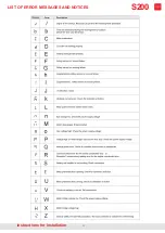
Page 20: ...20 instructions for installation LIST OF ERROR MESSAGES AND NOTICES S200 ...

Page 21: ...parameter setting MANDATORY PARAMETER 0 1 2 3 4 5 6 7 8 9 25 KG 50 KG 75 KG 100 KG 125 KG 150 KG 175 KG 200 KG 225 KG 250 KG 102 DOOR DIMENSIONS Only weights that the automation can manages safely can be enter based on the door weight parameter setting MANDATORY PARAMETER 0 1 2 3 4 5 6 7 8 9 500 mm 600 mm 700 mm 800 mm 900 mm 1000 mm 1150 mm 1300 mm 1450 mm 1600 mm 103 ARCHITRAVE DEPTH Defines the...

Page 22: ...inside to outside Enabled from outside to inside 107 FIRE ALLARM INPUT LOGIC A command on this input causes the door to open even when it is closing When this command is disabled the automation returns to the previous state 0 1 NO NC 108 INPUT OPEN A command on this input causes opening of the door even when it is closing 0 1 NO NC 109 HARD RESET Resets to the native state Serves to return the mac...

Page 23: ...ting an opening and closing cycle at low speed with safety sensors disabled a failure to comlete this sycle lights up an error it performs a NEAR at low speed till an opening and closing cycle is successfully completed with safety sensors enabled 118 FINAL TRACTION Serves to regulate the closing force and guarantee the closing of the door Adjustable from 0 to 9 0 1 2 3 4 5 6 7 8 9 Increasing the v...

Page 24: ...ON Regulates the force applied to the obstacle in full energy before stopping 0 1 2 3 4 5 6 7 8 9 0 is the minimum force and 9 is the greatest 125 ANTIWIND FORCE WITH CLOSED DOOR Force applied on closed door edge to prevent open ingn case of wind 0 1 2 3 4 5 6 7 8 9 Disabled Increasing the value increases the force 126 WIND RESISTANCE FORCE WITH OPEN DOOR Force applied on open door edge that preve...

Page 25: ...dicates who electronic lock is controlled Values from 5 to 8 s erve for locks that can work with 24V power panel with duty cycle at 50 0 1 2 3 4 5 6 7 8 No lock Lock if powered Lock if not powered Impulsive s electing the parameter with a value different of 0 Bistable One impulse opens and another closes Lock of powered at duty 50 Lock if not powered at duty 50 Impulsive at duty 50 Bistable One im...

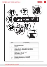
Page 26: ...26 instructions for installation PRE WIRED ELECTRIC CONNECTIONS S200 ...

Page 27: ...PRESS ENTER BUTTON The display shows ROT 4 Load as indicated Press and hold down DOWN BUTTON for 365 degree the plate will rotate clockwise load 5 Insert the screw at the BOARD SIDE GLS and tighten fully with an T Allen key 6 Press ENTER for ADJUSTAMENT The display shows END 7 Insert the screw at THE MOTOR SIDE SMS and tighten fully with an T Allen key Press ENTER The automation is now FULL LOADED...

Page 28: ...EASSEMBLY ARM REMOVAL 1 Make sure that the spring is locked by inserting both the grub screws GLM and GLS 2 Isert the extractor cap by screwing it clockwise 3 Turn the fastening screw anti clockwise so that it pushes on the extractor cap and removes the arm from its seat ...

Page 29: ...cks it with the electric lock signaling that the restroom is occupied Pressing the internal button opens the door if the door is not closed The door is equipped with an electric lock connected to the input board see pag 16 The external radar input 22 should be con nected to a button on the outside of the re stroom The internal radar board input 18 will be connected to a button on the inside of the...

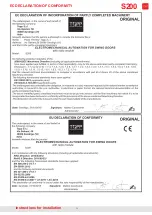
Page 30: ...30 EC DECLARATION OF CONFORMITY instructions for installation S200 ...

Page 31: ...31 instructions for installation S200 ...

Page 32: ... a direzione e coordinamento di 2 Plus 3 Holding S p a via Galvani 59 36066 Sandrigo VI tel 39 0444 656700 fax 39 0444 656701 www topp it info topp it INSTRUCTION for INSTALLATION Max capacity 250 Kg S200 instructions for installation ...

Reviews: