


4
GENERAL RECOMMENDATIONS
•
This manual provides all instructions necessary for correct installation and maintenance of the automation. Topp srl is not liable for any damages to persons,
animals and property caused by failure to comply with these instructions.
•
Before installing and using the automation the installer and user must read and thoroughly understand all parts of this manual.
•
This manual is an integral part of the automation and must be kept by the installer, with all the enclosures, for future reference.
•
The warranty is invalidated if use is made in any way not complying with the instructions and rules described in this manual, and if original parts, accessories,
replacements and control systems are not used.
•
Topp srl reserves the right to improve and amend the manual and products described at any time and without notice.
•
The information contained in this manual was written and checked with the maximum care; however, topp srl has no liability for any errors due to omissions or
errors in printing or transcription.
GENERAL SAFETY RULES
•
The operators must be informed about the risks of accidents, the safety devices for the operators and the general accident-prevention rules contemplated by
the international directives and laws in force in the country of use of the automation. The operators’ conduct must always scrupulously comply with the accident
prevention rules in force in the country in which the automation is used.
•
During handling and installation of the parts, the personnel shall be equipped with suitable personal protection equipment (PPE) so as to perform the works
required under safe conditions.
•
To prevent injury and risks for the health of the workers, the maximum limits shall be applied for manual handling of loads, as provided in standard ISO 11228-1.
•
Any unauthorized tampering or replacement of automation parts and any use of accessories or consumable materials different from the originals may cause a
risk of accidents and relieves the manufacturer from any civil and criminal liability.
•
For correct operation of the automation we recommend performing routine maintenance as indicated in paragraph 7 of this manual. Any operations of routine and
special maintenance that require even partial disassembly of the automation must be carried out only after disconnecting power to the automation.
•
Do not remove or alter the plates and labels applied by the manufacturer on the automation and its accessories.
•
It is strictly prohibited to hinder movement of the door and work near the hinges or mechanical moving parts (such as articulated or sliding arms).
•
The manufacturer has no liability for any damage caused by improper or unreasonable use of the automation.
•
When handling electronic parts always wear grounded antistatic conductive armbands as any electrostatic charges could damage the electronic parts on the
boards.
•
The electromechanical parts and electronic circuits necessary for control of the movement are protected by the aluminum casing.
•
His device may be used by children at least 8 or older, and by persons with reduced physical, sensorial or mental faculties, or lacking experience, only under direct
supervision or after they have received adequate instructions relative to its safe use.
•
Children should not play with the device.
PROPER AND IMPROPER USE
•
Automation S200 is designed and produced exclusively to operate (open and close) hinged doors and is intended for use in the residential, public and industrial
sectors.
•
It is strictly prohibited to use the automation for purposes other than those described, in order to guarantee the safety of the installer and user at all times and the
effective function of the automation.
•
Automation S200 in low energy operating mode can be installed in places where the door is used by disabled, elderly or fragile persons or persons with limited
motor capacity, after performing the risk analysis and considering that the risk for this type of user is low.
INSTALLER
•
Installation of the automation must be made exclusively by qualified technical personnel in possession of the professional requisites contemplated by the legisla
-
tion in force in the country of installation.
•
The installer must be able to install the automation and start it, and to operate in the presence of electrical power inside electric cabinets and shunt boxes. He must
be qualified to make all the necessary adjustments of an electrical and mechanical nature.
•
The use of parts, settings or processes not described in this document may cause electrical risks and/or hazards deriving from mechanical elements.
•
The installer shall check for conformity to the directives and regulations in force regarding the safe use of motor-operated doors.
•
After installing the automation, the installer shall perform an analysis of the risks and verify that the hinged door installation does not present risks in the points of
crushing or shearing and, if necessary, shall take adequate protective measures and apply the warning signs contemplated by the legislation in force to identify
hazardous areas.
•
Every installation shall display the identification of the motorized system in a clearly visible place.
•
The installer shall also provide the owner with all the information relative to automatic, manual and emergency operation of the automation, and shall deliver the
instructions for use to contained in this manual to the user.
•
He installer is the only person liable for erroneous installation and failure to comply with the instructions in this manual. The installer shall therefore respond on an
exclusive basis to the user and/or third parties for all damages to persons and/or property caused by erroneous installation.
•
Topp srl is not liable for the adequacy and strength of the doors to be motorized.
RISK ANALYSIS BY THE INSTALLER
IN ANY CASE, THE INSTALLER HAS SOLE LIABILITY FOR THE COMPLETE SAFETY OF THE HINGED DOOR AFTER ANALYZING THE RISKS, AS WELL
AS THE RESIDUAL RISKS. ALL IN RESPECT OF THE LEGISLATION IN FORCE IN THE COUNTRY IN WHICH IT IS INSTALLED.
•
The installer must evaluate and secure the system from risk of crushing, cutting, impact, trapping on the moving angles of closure and residual risks relative a
door movement..
•
The installer must evaluate and secure the system from risk of crushing and cutting between the levers or between the levers, the gliding guide and residual risks
relative a leaf movement..
USER
•
The user must be able to use the automation under normal conditions and to perform simple operations of startup or reset of the automation after a possible
forced interruption, through the use of the devices that serve for the purpose (program selector, digital switch, key switch, control buttons, etc.)
•
The user must not open the casing or perform any other operations reserved for maintenance personnel or specialized experts. In case of breakdown or malfunc-
tion of the door, the user shall only disconnect the circuit breaker and abstain from any other action or attempted repairs. use of the automation must be assigned
exclusively to users who comply with the instructions in this manual and in the manuals of the TOPP devices connected to it.
TECHNICAL ASSISTANCE
•
For assistance, contact the installer or retailer..
RATING PLATE AND “CE” MARKING
•
The “CE” marking certifies the conformity of the machine to the essential health and safety requisites foreseen by the European product directives. It is formed of
an adhesive plate made from polyester, screen printed black, with the following dimensions: W=50mm - H=36mm. It should be applied by the installation techni
-
cian in a clearly visible position on the outside of the automation unit.
RIGHTS RESERVED
•
All information (text, drawings, diagrams, etc.) presented here is reserved. No part of this manual may be reproduced or disclosed in any way, with any means of
reproduction (photocopies, microfilm or others) without the written authorization of the Manufacturer.
•
All rights regarding this manual of “Instructions for installation and use” remain the property of the Manufacturer.
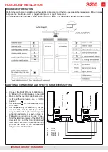
instructions for installation
GENERAL INFORMATION and SAFETY
S200
Summary of Contents for S200
Page 20: ...20 instructions for installation LIST OF ERROR MESSAGES AND NOTICES S200 ...
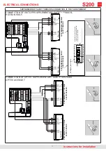
Page 26: ...26 instructions for installation PRE WIRED ELECTRIC CONNECTIONS S200 ...
Page 30: ...30 EC DECLARATION OF CONFORMITY instructions for installation S200 ...


