2.3
PACKAGE
Every standard package of the product (cardboard carton) contains (Fig.2):
–
No.1 linear automation ;
–
No. 1 rail ;
–
No. 1 rotor – rail connecting guide ;
–
No. 1 internal sensor ;
–
No. 1 interlocking gasket ;
–
No. 1 actuator fastening bracket ;
–
No. 2 rail fastening templates ;
–
No. 1 safety doorstop ;
–
No. 1 package of hardware consisting of : see picture;
–
No. 1 lateral cable fastening plug ;
–
No. 1 covering masks ;
–
No. 2 adhesive red labels covering screws.
Make sure the parts described above are in the package and check that the automation has not undergone any damage
during shipment. If anything is wrong, do not install the automation; you must request technical assistance from your
dealer or the manufacturer.
2.2
TECHNICAL DATA
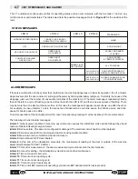
Tab. 1 lists the technical data that characterize the V1 automation.
POWER SUPPLY
MAXIMUM THRUST FORCE
PROTECTION AGAINST ELECTRIC SHOCKS
WORKING TEMPERATURE
NUMBER OF DOOR PANELS
Continuous
1 PANEL
MODEL
Tab.
1
POWER SUPPLY OUTPUT FOR PERIPHERALS
POWER ABSORBED
ABSORPTION
OPENING/CLOSING SPEED
WEIGHT CONTROL DOOR
DOOR OPEN WAITING TIME
TYPE OF OPERATION
MAXIMUM CAPACITY
WIDTH OF PASSAGEWAY
700÷1000 mm
1
3
4
5
6
7
8
9
V1
230 V 50 Hz
100 mA a 230 V
15 W
From 15 Kg to 70 Kg
67 N
adjustable 2s ÷ 60s
70 Kg
Class II
59 x59 x variable lenght
700 mm÷ 1000 mm
10
5 V 80 mA /24 V 110mA
11
12
In accordance with standard
En16005 “Low Energy Movement”
with reference to wing weight
OVERALL DIMENSIONS
2
Note 10N=approximately 1KG
POWER CORD (2X0.75mm²)
variable lenght 1400÷1700 mm
-5°C
+50°C
22
INSTALLATION AND USE INSTRUCTIONS
EN
V1
N.1 TSC Ph M4x20
N.5 TSP PZ 2.5x20
N.4 AF TC 3x16
N.10
N.10
9
Aluminium screws
2.9x13
Wood screws 3x20
Summary of Contents for V1
Page 2: ...2 ISTRUZIONI PER L INSTALLAZIONE E L USO IT V1 ...
Page 35: ...IT 7 FIGURE Fig 6 misura measurement X Fig 7 2cm 35 V1 FIGURE max 250mm A ...
Page 36: ...Fig 9 Fig 8 250mm 12mm 12mm 36 FIGURE V1 ...
Page 40: ...10 Fig 20 Fig 19 V1 FIGURE 40 ...
Page 41: ...Fig 21 41 V1 FIGURE ...
Page 43: ...Fig 23 TOPP V1 TOPP V1 43 V1 FIGURE ...
Page 44: ...Fig 24 a b c d e f V1 FIGURE 40 44 ...
Page 45: ... 45 V1 FIGURE ...
Page 46: ... V1 FIGURE 40 46 ...
Page 47: ......

