Fig.
3
VL
VPA
A
56
A
Fig.
4
VPA
VL
A
A
56
VPA
= net doorway width
VL
= gross opening 700÷1000
VPA
= net doorway width
VL
= gross opening 700÷1000
1 Wing with the opening toward the right
1 Wing with the opening toward the left
Fig.
2
3
4
1
5
2
7
8
9
10
11
12
6
2.4
TYPES OF APPLICATIONS
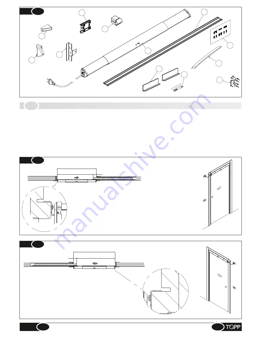
The automation unit can be used for two different applications:
Ÿ
automation for 1 wing with the opening toward the right (seen from the front of the automation), as shown in Fig. 3;
Ÿ
automation for 1 wing with the opening toward the left (seen from the front of the automation), as shown in Fig. 4.
Installation of V1 automation reduces the minimum opening width by about 56 mm (Fig. 3-4).
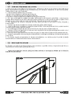
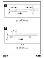
WARNING! Check that the safety distances indicated in the diagram are observed. These distances prevent
fingers from being dragged into the door and prevent crushing, dragging and amputation (Fig.A-B).
23
EN
INSTALLATION AND USE INSTRUCTIONS
V1
Summary of Contents for V1
Page 2: ...2 ISTRUZIONI PER L INSTALLAZIONE E L USO IT V1 ...
Page 35: ...IT 7 FIGURE Fig 6 misura measurement X Fig 7 2cm 35 V1 FIGURE max 250mm A ...
Page 36: ...Fig 9 Fig 8 250mm 12mm 12mm 36 FIGURE V1 ...
Page 40: ...10 Fig 20 Fig 19 V1 FIGURE 40 ...
Page 41: ...Fig 21 41 V1 FIGURE ...
Page 43: ...Fig 23 TOPP V1 TOPP V1 43 V1 FIGURE ...
Page 44: ...Fig 24 a b c d e f V1 FIGURE 40 44 ...
Page 45: ... 45 V1 FIGURE ...
Page 46: ... V1 FIGURE 40 46 ...
Page 47: ......

