3.7
RESIDUAL HAZARDS
The analysis of essential safety requisites for safeguarding health, performed by TOPP Srl on the basis of Machine
Directive 2006/42/CE, refers to a “typical” installation site and user adequate for the type of machine that will be produced.
Any procedure, installation type or adjustment not detailed or mentioned in this manual is prohibited in that it could give
rise to hazards and risks.
IT
USE AND OPERATION
4
4.1
TECHNICAL DESCRIPTION
The V1 automation unit is a Low Energy unit and is therefore considered as safe without additional safety devices.
The automation is a mechnical type with no clutch or brakes, so as to prevent possible blockages of a continuous
character due to damage or breakage of the structure.
The power supply is 230V~ 50 Hz.
The electronic command and control board is a microprocessor type with keys along the edge for adjustment of such
parameters as speed of opening and closing, slowing space, low approach speed, automatic return to the closed position,
timing and mode of operation.
The automation is equipped with various functions, such as:
- Pull & go, which permits automatic movement of the door if pushed or pulled s
lightly;
- ultraslow nighttime function (can be selected with the remote control), which reduces the noise;
- the possibility of connection to the domotic network via Bus (up to 63 actuators usable in a single network).
In the event of a power supply failure, the automation unit may be set up to perform an automatic reset cycle of the door
functions.
27
EN
INSTALLATION AND USE INSTRUCTIONS
V1
CONNECTION TO SENSORS (OPTIONAL ACCESSORIES)
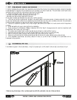
For the installation of sensors or buttons on the part opposite the automation unit, follow the instructions in the
associated manuals (see also section on spare parts and accessories).
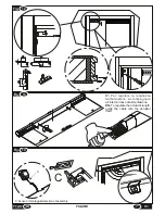
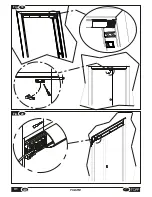
For cabling routes and electronic connection refer to
figures 21-22.
3.6
Summary of Contents for V1
Page 2: ...2 ISTRUZIONI PER L INSTALLAZIONE E L USO IT V1 ...
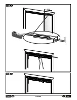
Page 35: ...IT 7 FIGURE Fig 6 misura measurement X Fig 7 2cm 35 V1 FIGURE max 250mm A ...
Page 36: ...Fig 9 Fig 8 250mm 12mm 12mm 36 FIGURE V1 ...
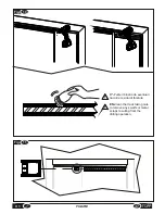
Page 40: ...10 Fig 20 Fig 19 V1 FIGURE 40 ...
Page 41: ...Fig 21 41 V1 FIGURE ...
Page 43: ...Fig 23 TOPP V1 TOPP V1 43 V1 FIGURE ...
Page 44: ...Fig 24 a b c d e f V1 FIGURE 40 44 ...
Page 45: ... 45 V1 FIGURE ...
Page 46: ... V1 FIGURE 40 46 ...
Page 47: ......

