background image

After making this adjustment, connect the actuator to the power supply to perform the initialization procedure.

F

Before performing the initialization procedure, open the door manually by about 10 cm. This is necessary only at the 

time of starting the automation. 

WARNING: During the procedure do not disconnect the power, do not open or close the door manually and do 
not touch any of the keys on the electronic board.
WARNING

During  the  initialization  and  reset  procedures  all  controls  (sensors,  remote  controls,  etc.)  are 

blocked. Therefore, stand clear of the door operating area.

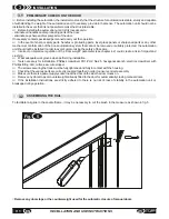
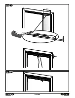
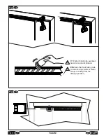
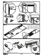
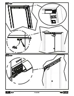
Access the automation unit's electronic circuit board as shown in 

fig.20.

 If the cover does not slide easily, remove the actuator from its location and try again

.

-

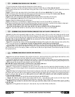
Figure 22

: Press key S1 for about seven seconds. At this point the automation will start the procedure of searching for 

the limit switches; wait until it has completed this process. The door performs two opening and closing cycles, after which 
the automation is ready to use. 

 WARNING! The initialisation procedure must be repeated each time the automation unit is given new settings. 

After initialization, the "standing by for open command" status is confirmed by LED L2 on with fixed green light. 
This status remains unchanged until the door is commanded to open, and returns at the end of the open/close cycle.
If,  during  the  initialization  procedure,  the  door  does  not  reach  the  limit  switches  correctly,  repeat  the  procedure, 
accompanying the door so that it completes the cycle. This situation could indicate the presence of excessive friction on 
the glide of the door, excessive weight of the door or an improper reading of its position by the actuator. 
If the door does not move correctly after the second initialisation procedure, check there are no obstacles or impediments, 
check the weight of the door and change the settings if required.  Repeat the initialisation procedure.
If the problem persists, disconnect the automation unit from the power supply and contact the technical assistance 
service.

Note: the Pull&go function becomes active once again 5 seconds after the initialisation procedure is completed.

After the initialization procedure, close the sliding cover on the board.

29

EN

INSTALLATION AND USE INSTRUCTIONS

V1

4.4

INITIALISATION PROCEDURE


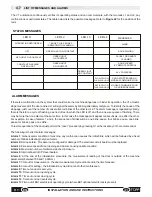
There are 10 dipswitches (microswitches) on the circuit board, accessible by opening the cover on the control board 
(Figure 20).
Each dip-switch (Figure 22 reference “C”) can be set in 2 positions, marked ON and OFF. 
At the first use, all the dipswitches are set in the OFF position except dips 9-10, which is set to ON.

Hereafter we indicate the functions of each dipswitch.

-DIP-SWITCH No.10: 

When set to 

ON

, in case of power outage, the reset procedure is performed automatically when 

power returns. If set to 

OFF

 the automation unit awaits a manual reset procedure.

In case of collision:

 if set to

 OFF

, when an impact occurs the automation unit cuts off the power supply  and runs a reset 

procedure after 5 seconds; in case the obstacle remains, the door panels remain free until the manual reset procedure 
has been performed. If set to 

ON

, in the event of collision the door automatically performs a reset; following the fourth 

impact, the automation unit cuts off the power supply to the motor for 15 minutes, after which it automatically carries out 
the reset procedure.

-DIP-SWITCH No. 9: 

If switch to the 

ON

 position, makes the door close very slowly, regardless of the weight selected on 

switch "A".

-DIP-SWITCH No. 8: 

: When set to 

ON

, causes the door to stop gradually when opening (soft stop). This function was 

created for relatively lightweight doors; if the door is moderately or very heavy, the door may not complete the opening 
cycle, so it is advisable to set it to the 

OFF

 position.

-DIP-SWITCH No. 7:

 If electric lock EB1 (optional accessory), or another device is fitted, set to 

ON

; if no electric lock is 

present, set to 

OFF

.

-DIP-SWITCHES no. 6-5-4-3-2-1: 

These are used to set the door address. In case of a single door, all the dip-switches 

must be set to 

OFF

4.3

PROGRAMMING THE DIP-SWITCH
   

Summary of Contents for V1

Page 1: ...I PER L INSTALLAZIONE E L USO INSTALLATION AND USE INSTRUCTIONS IT EN pag 3 pag 19 AUTOMAZIONE PER PORTE SCORREVOLI LINEARI AD UNA ANTA AUTOMATION FOR ONE LEAF SLIDING LINEAR DOORS Istruzioni originali Original instructions BREVETTATO PATENTED ...

Page 2: ...2 ISTRUZIONI PER L INSTALLAZIONE E L USO IT V1 ...

Page 3: ...ore pag 10 3 5 Montaggio dell attuatore sull anta pag 10 3 6 Collegamento ai sensori di rilevamento accessori opzionali pag 11 3 7 Rischi residui pag 11 4 USO E FUNZIONAMENTO 4 1 Descrizione tecnica pag 11 4 2 Procedura regolazione peso e tempo apertura pag 12 4 3 Programmazione di dip switch pag 13 4 4 Procedura di inizializzazione pag 13 4 5 Procedura di reset pag 14 4 6 Regolazione raggio d azi...

Page 4: ...ericoli e o danni E vietata qualsiasi modifica e o alterazione dell automazione perche potrebbe essere causa di gravi pericoli e o danni Qualunque manomissione o sostituzione non autorizzata di parti o componenti dell automazione e l utilizzo di accessori o materiali di consumo diversi dagli originali possono rappresentare un rischio di incidente e solleva il costruttore da qualunque responsabilit...

Page 5: ...vo di intervento o riparazione non contemplate nella voce problemi e loro rimedi L utilizzo dell automazione deve essere esclusivamente assegnata a utenti che agiscono in conformità alle istruzioni riportate nel presente manuale e nei manuali dei dispositiviTOPPSrl ad esso collegati 2 1 DESTINAZIONE D USO L automazione V1 serve per motorizzare porte scorrevoli pedonali da interno ad anta singola c...

Page 6: ...ti i dati tecnici che caratterizzano l automazione V1 TENSIONE DI ALIMENTAZIONE FORZA MASSIMA DI SPINTA CLASSE DI ISOLAMENTO TEMPERATURA DI FUNZIONAMENTO NUMERO DI ANTE Utilizzo continuo 1 ANTA MODELLO Tab 1 USCITA ALIMENTAZIONE PERIFERICHE POTENZA ASSORBITA ASSORBIMENTO VELOCITÀ APERTURA CHIUSURA REGOLAZIONE PESO ANTA TIMER SOSTA PORTA APERTA TIPO DI FUNZIONAMENTO DIMENSIONI DI INGOMBRO PORTATA M...

Page 7: ...vede una riduzione della larghezza del vano passaggio minima di circa 56mm Fig 3 4 ATTENZIONE Verificare la presenza delle distanze di sicurezza indicate in figura necessari ad impedire possibili trascinamenti delle dita all interno della porta e ad evitare pericoli di schiacciamento convogliamento o cesoiamento Fig A B 7 IT ISTRUZIONI PER L INSTALLAZIONE E L USO V1 Fig 4 1 Anta con apertura verso...

Page 8: ...Figura A se S 8mm allora t 0 se S 8mm allora t 25 Figura B se S 8mm allora Y 0 se S 8mm allora Y 25 8 ISTRUZIONI PER L INSTALLAZIONE E L USO IT V1 A B ...

Page 9: ...arsi di guanti protettivi adeguati Utensili necessari per l installazione cacciavite a stella PH1 PH2 chiave esagonale da 2 5mm avvitatore elettrico con inserto a stella trapano seghetto spellafili Le viti di fissaggio del binario devono essere strette a fondo e devono essere in battuta nella sede Verificare il corretto accoppiamento tra i vari pezzi al fine di garantire che tutti gli assemblaggi ...

Page 10: ...3 viti TSP PZ 2 5X20 Attenzione le viti sono adatte all utilizzo su legno per altri materiali rivolgersi al costruttore o all assistenza tecnica autorizzata Figura 13 Allentare leggermente le quattro viti poste sul retro dell attuatore vedi Figura 13 e regolarlo in lunghezza nella misura pari a quella della porta meno circa 20mm Accompagnare il cavo di alimentazione all interno dell attuatore FIn ...

Page 11: ... tasti a bordo per la regolazione dei parametri quali velocità di apertura e chiusura spazio rallentamenti bassa velocità di accostamento tempo richiusura automatica e modalità di funzionamento L automazione è dotata di varie funzionalità tra le quali funzione Pull go che consente il movimento automatico della porta se viene leggermente spinta o tirata funzionamento notturno ultraslow selezionabil...

Page 12: ...lle porte e le formule per il calcolo del volume e del peso della porta Topp declina ogni responsabilità per quanto attiene al calcolo del peso dell anta e del materiale che la costituisce Dove V volume dell anta espresso in m L larghezza dell anta in metri H altezza dell anta in metri S spessore dell anta in metri Dove P peso dell anta espresso in kg V volume dell anta espressa in m calcolato sop...

Page 13: ...tecnica Nota la funzione Pull go ritorna ad essere attiva solo dopo un tempo di attesa di 5 sec dalla procedura di inizializzazione Al termine della procedura di inizializzazione richiudere il coperchio a scorrimento sopra la scheda 4 4 PROCEDURA DI INIZIALIZZAZIONE 13 IT ISTRUZIONI PER L INSTALLAZIONE E L USO V1 I dip switch sono 10 micro interruttori presenti sulla scheda e accessibili aprendo i...

Page 14: ... RESET 4 7 FUNZIONE DI APERTURA E CHIUSURA TEMPORIZZATA ATTENZIONE per utilizzare questa funzionalità è obbligatorio essere muniti di telecomando TS8 elettroblocco EB1 e due pulsanti a sfioramento HS2 Per attivare la funzione temporizzata estrarre il sensore interno staccare il connettore e inserirlo nuovamente nella sede assicurandosi che i cavi piatti del sensore siano disposti in maniera ordina...

Page 15: ...appariranno consecutivi uno all altro Per esempio se gli allarmi saranno il n 1 e il n 4 la sequenza dei lampeggi sarà un lampeggio pausa quattro lampeggi pausa un lampeggio pausa quattro lampeggi pausa un lampeggio Per ripristinare il funzionamento della porta sarà sufficiente eseguire la procedura di reset tramite la pressione del pulsante S1 o con l apposito tasto sul telecomando Di seguito si ...

Page 16: ...erventi sull automazione diversi da quelli sopracitati non autorizzati daTOPPSrl non sono permessi 5 2 ACCESSORI E RICAMBI A RICHIESTA È vietato l impiego di ricambi ed accessori non originali che possono compromettere la sicurezza e l efficienza dell automazione I ricambi e gli accessori originali devono essere richiesti esclusivamente al rivenditore di fiducia o al fabbricante comunicando tipo m...

Page 17: ...almente ma dopo tre aperture si richiude a velocità ridotta e alla quarta segnala allarme impatto Assicurarsi che non ci siano ostacoli nel vano passaggio Allarme 1 Eseguire procedura di reset e se necessario procedura di inizializzazione Allarme 3 Allarme 5 Eseguire procedura di inizializzazione PROBLEMA RIMEDIO 5 4 PROBLEMI E LORO RIMEDI Eseguire procedura di reset e se necessario procedura di i...

Page 18: ...03TB01112 al n 1612PF01999 è in conformità a tutti i requisiti applicabili delle seguenti direttive CE incluse tutte le revisioni applicabili Direttiva Macchine 2006 42 CE Recepimento Italiano DLgs 27 gennaio 2010 n 17 Direttiva Compatibilità Elettromagnetica 2014 30 UE Direttiva Rohs II 2011 65 UE Direttiva R TTE 2014 53 UE e che sono state utilizzate le seguenti norme armonizzate EN 16005 EN 610...

Page 19: ... Connection to sensors optional accessories page 27 3 7 Residual hazards page 27 4 USE AND OPERATION 4 1 Technical description page 27 4 2 Procedure for adjustment of the weight and opening time page 28 4 3 Programming the dip switches page 29 4 4 Initialisation procedure page 29 4 5 Reset procedure page 30 4 6 Internal sensor detection area adjustment page 30 4 7 Timer mode opening and closing fu...

Page 20: ... and or damage Any modification and or alteration made to the automation unit is prohibited in that it may cause serious hazards and or damage Any unauthorized tampering or replacement of automation parts and any use of accessories or consumable materials different from the originals may cause a risk of accidents and relieves the manufacturer of any civil and criminal liability This manual was wri...

Page 21: ... is not listed in the troubleshooting section Use of the automation must be assigned exclusively to users who comply with the instructions in this manual and in the manuals of theTOPPSrl devices connected to it 2 1 INTENDED USE The V1 automation unit can be used to motorise internal sliding doors for pedestrians with a single doorway sized between 700mm and 1000mm and with an overall weight of bet...

Page 22: ...s the technical data that characterize the V1 automation POWER SUPPLY MAXIMUM THRUST FORCE PROTECTION AGAINST ELECTRIC SHOCKS WORKING TEMPERATURE NUMBER OF DOOR PANELS Continuous 1 PANEL MODEL Tab 1 POWER SUPPLY OUTPUT FOR PERIPHERALS POWER ABSORBED ABSORPTION OPENING CLOSING SPEED WEIGHT CONTROL DOOR DOOR OPEN WAITING TIME TYPE OF OPERATION MAXIMUM CAPACITY WIDTH OF PASSAGEWAY 700 1000 mm 1 3 4 5...

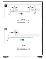
Page 23: ...mation for 1 wing with the opening toward the right seen from the front of the automation as shown in Fig 3 Ÿ automation for 1 wing with the opening toward the left seen from the front of the automation as shown in Fig 4 Installation of V1 automation reduces the minimum opening width by about 56 mm Fig 3 4 WARNING Check that the safety distances indicated in the diagram are observed These distance...

Page 24: ...Fig A If S 8mm then t 0 If S 8mm then t 25 Fig B If S 8mm then Y 0 If S 8mm then Y 25 A B 24 INSTALLATION AND USE INSTRUCTIONS EN V1 ...

Page 25: ...mpromising the safety of the same Incorrect or imprecise regulation of the door weight parameter see chapter 4 2 could create a risk of impact and crushing Wear adequate work gloves when performing installation Tools necessary for installation Phillips screwdriver PH1 PH2 No 2 5 hexagonal wrench electric screwdriver with Phillips fitting drill cutter saw wire stripper The screws securing the track...

Page 26: ...nstalled on the side of the door where the rail has already been installed Fasten the bracket to the frame using threeTSP2 5x20 screws Attention the screws provided are suitable for use on wood for other materials contact the manufacturer or an authorised technical assistance centre Figure 13 Loosen the four screws on the back see fig 13 and adjust the length to the same measurement as that of the...

Page 27: ...processor type with keys along the edge for adjustment of such parameters as speed of opening and closing slowing space low approach speed automatic return to the closed position timing and mode of operation The automation is equipped with various functions such as Pull go which permits automatic movement of the door if pushed or pulled slightly ultraslow nighttime function can be selected with th...

Page 28: ...sing the electronic circuit board in the automation unit fig 20 The door open time can be regulated between a minimum of 2 seconds and a maximum of 60 4 2 PROCEDURE FOR ADJUSTMENT OF THE WEIGHT AND OPENING TIME Before activating the automation unit the opening and closing speed must be regulated to match the door weight by accessing the electronic circuit board in the automation unit see fig 20 Th...

Page 29: ...persists disconnect the automation unit from the power supply and contact the technical assistance service Note the Pull go function becomes active once again 5 seconds after the initialisation procedure is completed After the initialization procedure close the sliding cover on the board 29 EN INSTALLATION AND USE INSTRUCTIONS V1 4 4 INITIALISATION PROCEDURE There are 10 dipswitches microswitches ...

Page 30: ... CAUTION to use this function it is necessary to have a TS8 remote control EB1 electric lock and two Hs2 touch controls To activate the timer mode function extract the internal sensor remove the connector then insert it back into its housing while making sure that the flat sensor cables are neatly arranged inside the actuator Mount the two HS2 touch controls one inside and the other outside the ro...

Page 31: ...ashing There may be more than one alarm at the same time In this case the messages will appear consecutively one after the other For example in case of alarms 1 and 4 the sequence of blinks will be one blink pause four blinks pause one blink pause for blinks pause one blink To restore operation of the door just perform the reset procedure by pressing S1 or the reset key on the remote control The f...

Page 32: ...ted above must be authorized by TOPP Srl Unauthorized repairs are not permitted 5 2 SPARE PARTS AND ACCESSORIES AVAILABLE ON REQUEST Always use original spare parts and accessories to ensure the safety and efficient operation of the automation and avoid invalidating the warranty Original spare parts and accessories must be ordered exclusively from the dealer or manufacturer communicating the type ...

Page 33: ...r three openings closes slowly and at the fourth signals the collision alarm Make sure there are no obstacles in the passage space Alarm 1 Perform the reset procedure and if necessary repeat initialization Alarm 3 Alarm 5 Perform the initialization procedure PROBLEM REMEDY 5 4 TROUBLESHOOTING Perform the reset procedure and if necessary repeat initialization Alarm 4 Perform the reset procedure All...

Page 34: ...umber and year of construction from no 1603TB01112 to no 16120PF1999 is in conformity with all the relevant provisions of the following EC directive s including all applicable amendments Machinery Directive 2006 42 EC Italian adoption DLgs 27 Jan 2010 n 17 EMC Directive 2014 30 EU Rohs II Directive 2011 65 EU R TTE Directive 2014 53 EU and that the following harmonised standards have been applied ...

Page 35: ...IT 7 FIGURE Fig 6 misura measurement X Fig 7 2cm 35 V1 FIGURE max 250mm A ...

Page 36: ...Fig 9 Fig 8 250mm 12mm 12mm 36 FIGURE V1 ...

Page 37: ...Fig 10 IT Pulire il binario da eventuali trucioli e residui di foratura EN Clean the track taking care to remove any swarfs or metal scraps resulting from the drilling operation 37 V1 FIGURE Fig 11 ...

Page 38: ...ction of assembly C Fig 12 Fig 14 C Fig 13 VL 20mm IT Per regolare la lunghezza dell attuatore accompagnare all interno il cavo di alimentazione EN To regulate the actuator length guide the cable into the actuator itself 38 FIGURE V1 15 30 10 8 ...

Page 39: ...Fig 17 Fig 16 Fig 18 A ATTENZIONE Prestare attenzione a non deformare la superficie esterna in plastica CAUTION Be careful not to deform the outer surface of plastic 39 V1 FIGURE Fig 15 1 2 34 5 ...

Page 40: ...10 Fig 20 Fig 19 V1 FIGURE 40 ...

Page 41: ...Fig 21 41 V1 FIGURE ...

Page 42: ...elativo manuale Connector for connecting sensor button on the side opposite the automation unit See the associated manual for the installation of electric lock EB1 Prestare attenzione che il ponticello sia sempre presente Make sure that the b r i d g e i s a l w a y s present C A D E S1 S2 L3 L4 B L1 L2 C A D E S1 S2 L3 L4 B L1 L2 Prestare attenzione che il ponticello sia sempre presente Make sure...

Page 43: ...Fig 23 TOPP V1 TOPP V1 43 V1 FIGURE ...

Page 44: ...Fig 24 a b c d e f V1 FIGURE 40 44 ...

Page 45: ... 45 V1 FIGURE ...

Page 46: ... V1 FIGURE 40 46 ...

Page 47: ......

Page 48: ...TOPP S r l Società a Socio Unico soggetta a direzione e coordinamento di 2 Plus 3 Holding S p a Via Galvani 59 36066 Sandrigo VI Italia Tel 39 0444 656700 Fax 39 0444 656701 Info topp it www topp it ...

Reviews: