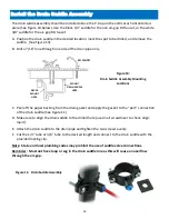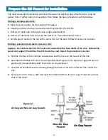
12
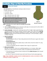
Connect the System
WOW RO System
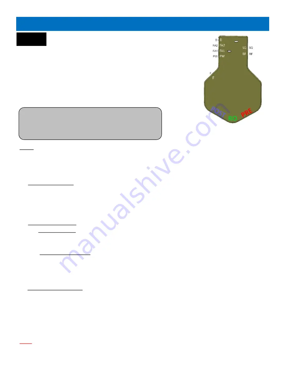
port identification markings molded into top of
manifold: (See Figure 4).
•
F:
Feed (¼
”
red)
•
D:
Drain (¼
”
black)
•
FA1:
Faucet/Accessory 1 (⅜
”
blue)
•
FA2:
Faucet/Accessory 2 (¼
”
blue)
•
PW:
Used for testing or additional storage.
•
SQ:
Used for testing or additional storage.
•
RF:
Do not touch (pre
-
connected).
NOTE: Ports that are not used require the appropriate sized plug.
(Included).
A.
With the
WOW RO System
in place, remove any port plugs as necessary (push in white collet to
release) and make the following connections:
B.
Feed F connection:
Take the
1/4”
red tubing and snip off a
6”
length. Take long end of remain-
ing tubing and attach to feed water adapter (cold water supply). Attach other end to
WOW RO
System
emergency shut
-
off valve (in installation kit). With
6”
tubing, attach one end to
WOW
RO System
emergency shut
-
off valve and the other end to gray
“
F
”
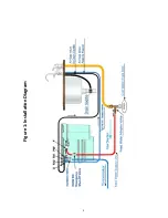
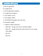
port (See Figure 1, Page 4:
Installation Diagram).
C.
Drain D connection:
i.
Air
-
Gap Faucet
Route the free end of the
1/4”
black tubing attached to the RO faucet air
-
gap to the connec-
tion marked
“
D
”.
ii.
Non Air
-
Gap Faucet *
Route drain line connection (saddle clamp or other) to the connection marked
“
D
”,
using
the
1/4”
black tubing.
*
Check local plumbing codes for compliance when using non air
-
gap faucets.
D.
RO Faucet connection:
FA1
(3/8”)
or FA2
(1/4”)
If there are no additional appliances (i.e. icemaker, coffee maker,
cooler, etc.) to hook up then you have the choice of using either port for the RO faucet.
i.
If the RO faucet is more than ten feet in distance from the
WOW RO System
, then the
3/8”
FA1 port is preferred.
ii.
Use the
1/4”
FA2 port for the RO faucet and the
3/8”
FA1 port for the added appliances.
Note: If your installation needs to connect to multiple appliances, such as an icemaker or coffee
maker, go to Section 2, Pages 15
-
21
Installation Steps and Start
-
Up Procedures
Step 4
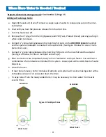
Figure 4:
System Connections
Summary of Contents for WOW RO System
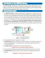
Page 4: ...4 Figure 1 Installation Diagram...
Page 5: ...5 Section 1 Installation Start up Procedures...
Page 8: ...8 Installation Kit Contents A B C D E F G H I G...
Page 17: ...17 Figure 7 Refrigerator Icemaker...
Page 24: ...24 Modular Expandability Parallel Processing...
Page 25: ...25 Section 4 Plumbing the Sink...
Page 29: ...29 Section 5 Maintenance...
Page 35: ...35 Section 6 Troubleshooting...


