background image


Page 49 


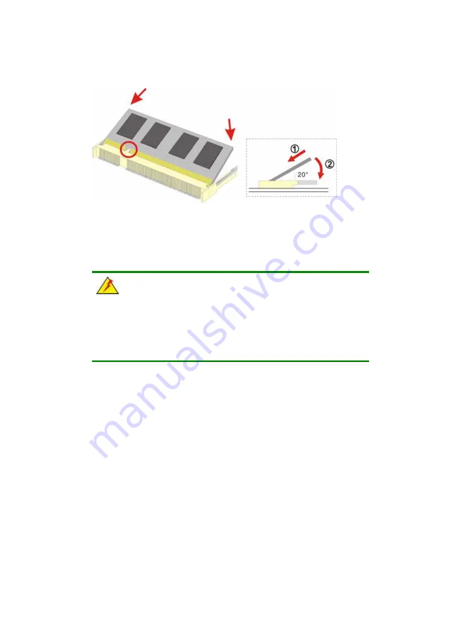
Figure 3-10: SO-DIMM Module Installation   


3.10 Mounting the System 


WARNING!


When mounting the flat panel PC onto an arm, onto the wall or onto a 

panel, it is better to have more than one person to help with the installation 

to make sure the panel PC does not fall down and get damaged. 

The four methods of mounting the EX-93821/EX-93823 are listed below. 


Wall mounting 


Panel mounting 


Arm mounting 


Rack mounting 

The four mounting methods are described below. 

3.10.1 Wall Mounting 

To mount the flat panel PC onto the wall, please follow the steps below. 

Step 1: 

Select the location on the wall for the wall-mounting bracket.   

Summary of Contents for EX-93821

Page 1: ...Page 1 EX 93821 EX 93823 Flat Panel PC...

Page 2: ...X 93821 EX 93823 Flat Panel PC Page 2 Revision Date Version Changes 2008 04 1 02 Added EX 93821GHS high luminance panel information 2007 08 1 01 Modified some specs errors 2007 07 1 00 Initial release...

Page 3: ...of the use or inability to use the product or documentation even if advised of the possibility of such damages This document contains proprietary information protected by copyright All rights are res...

Page 4: ...warning message is shown below WARNING This is an example of a warning message Failure to adhere to warning messages may result in permanent damage to the EX 93821 EX 93823 or personal injury to the u...

Page 5: ...These messages should be read carefully as any directions or instructions contained therein can help avoid making mistakes Notes are easy to recognize The word note is written as NOTE both capitalize...

Page 6: ...t an TOPSCCC sales representative please send an email to sales TOPSCCC com tw The items listed below should all be included in the EX 93821 EX 93823 package 1 x EX 93821 EX 93823 flat panel PC 1 x Po...

Page 7: ...SPECIFICATIONS 19 1 4 1 Preinstalled Hardware Components 19 1 4 2 System Specifications 19 1 4 3 Motherboard Specifications 21 1 4 4 Flat Panel Screen Specifications 22 1 4 4 1 EX 93821 Flat Panel Scr...

Page 8: ...37 3 4 1 Packing List 38 3 4 2 Optional Items 39 3 5 COMPACTFLASH CARD INSTALLATION 40 3 6 REMOVE THE BACK COVER 41 3 7 JUMPER SETTINGS 42 3 7 1 AT ATX Power Select 42 3 7 2 COM3 Pin 9 Signal Select...

Page 9: ...lat Panel Configuration 79 5 5 INTEGRATED PERIPHERALS 82 5 6 POWER MANAGEMENT SETUP 87 5 7 PNP PCI CONFIGURATIONS 94 5 8 PC HEALTH STATUS 97 A SAFETY PRECAUTIONS 99 A 1 SAFETY PRECAUTIONS 100 A 1 1 Ge...

Page 10: ...821 EX 93823 Flat Panel PC Page 10 D HAZARDOUS MATERIALS DISCLOSURE 117 D 1 HAZARDOUS MATERIAL DISCLOSURE TABLE FOR IPB PRODUCTS CERTIFIED AS ROHS COMPLIANT UNDER 2002 95 EC WITHOUT MERCURY 118 E INDE...

Page 11: ...5 COM1 and COM2 Pin 9 Signal Select Jumper Location 45 Figure 3 6 COM2 Select Jumper Location 46 Figure 3 7 HDD Bracket Retention Screws 47 Figure 3 8 EX 93821 EX 93823 HDD Bracket Retention Screws 4...

Page 12: ...EX 93823 TFT LCD Monitor Specifications 24 Table 2 1 Geode LX Graphics Features 31 Table 3 1 Package List Contents 39 Table 3 2 Optional Items 40 Table 3 3 Jumpers 42 Table 3 4 AT ATX Power Select Jum...

Page 13: ...Page 13 1 Introduction Chapter 1...

Page 14: ...ess Module EXMB LX 800 T R AMD Geode LX 800 10 4 230 cd m2 No EXMB LX 800 W T R AMD Geode LX 800 10 4 230 cd m2 Yes EX 93821GHS CPU LCD Brightness Wireless Module EXMB LX 800 T R AMD Geode LX 800 10 4...

Page 15: ...tion process RoHS compliance 1 2 External Overview 1 2 1 General Description The EX 93821 EX 93823 flat panel PC is a rectangular cubic structure that comprises of a screen rear panel top panel bottom...

Page 16: ...r to Figure 1 2 Figure 1 2 EX 93821 Rear View 1 2 4 Top Panel The top panel of EX 93821 EX 93823 provides access to three retention screws that support to secure the back cover to the chassis A connec...

Page 17: ...following I O interfaces Figure 1 4 1 x PS 2 keyboard mouse connector 1 x Audio jack 1 x VGA connector 1 x AC power adapter connector 1 x Power switch 2 x Serial port COM connectors 2 x RJ 45 10 100M...

Page 18: ...re 1 5 EX 93823 Bottom View 1 2 6 Side Panel The EX 93821 93823 has two side panels left panel and right panel Both side panels have retention screw holes that secure the back cover to the chassis The...

Page 19: ...circuit board that is connected to the screen and the motherboard 1 4 Specifications 1 4 1 Preinstalled Hardware Components The EX 93821 EX 93823 flat panel PC has the following preinstalled component...

Page 20: ...50 000 hrs 50 000 hrs Touch Screen 5 wire resistive type touch screen Drive Bay One 2 5 IDE HDD bay I O 2 x USB 2 0 ports 1 x keyboard mouse port 1 x VGA port 2 x LAN 1 x RS 232 1 x RS 232 422 485 1 x...

Page 21: ...Certificate Meets CE FCC Table 1 2 EX 93821 EX 93823 Specifications 1 4 3 Motherboard Specifications The EX 93821 and EX 93823 both come with an EXMB LX 800 motherboard The technical specifications of...

Page 22: ...rboard Specifications 1 4 4 Flat Panel Screen Specifications 1 4 4 1 EX 93821 Flat Panel Screen Specifications The EX 93821 comes with a TFT LCD monitor at the front of the flat panel PC see Figure 1...

Page 23: ...ecifications 1 4 4 2 EX 93823 Flat Panel Screen Specifications The EX 93823 comes with a TFT LCD monitor at the front of the flat panel PC see Figure 1 1 The specifications for the EX 93823 LCD monito...

Page 24: ...Flat Panel PC Page 24 SPECIFICATION EX 93823 Power Consumption W 4 Supply Voltage V 3 3 Backlight 2 CCFL Outline Dimensions mm 260 x 204 x 12 2 Backlight MTBF hrs 50000 Table 1 5 EX 93823 TFT LCD Moni...

Page 25: ...Page 25 1 5 Dimensions 1 5 1 EX 93821 Dimensions The dimensions of the EX 93821 flat panel PC are shown in Figure 1 7 below Figure 1 7 EX 93821 Dimensions units in mm...

Page 26: ...EX 93821 EX 93823 Flat Panel PC Page 26 1 5 2 EX 93823 Dimensions The dimensions of the EX 93823 flat panel PC are shown in Figure 1 8 below Figure 1 8 EX 93823 Dimensions units in mm...

Page 27: ...Page 27 2 Motherboard Chapter 2...

Page 28: ...D Geode LX 800 500MHz Specifications The specifications for the 500MHz AMD Geode LX 800 are listed below x86 x87 compatible core Processor frequency up to 500 MHZ 64K I 64K D L1 cache and 128K L2 cach...

Page 29: ...tem chipset features are listed below GeodeLink Interface Unit o 64 bit 66MHz operation o PCI VSM Virtual System Module that makes the interface transparent to applications software and BIOS o Program...

Page 30: ...cs Processor is a BitBLT vector engine that supports pattern generation source expansion pattern source transparency 256 ternary raster operations alpha blenders to support alpha BLTs incorporated BLT...

Page 31: ...ize Mono 8x8 pixels Pattern Size Color 8x8 pixels Monochrome Pattern Yes with inversion Dithered Pattern 4 color No Color Pattern 8 16 32 bpp Transparent Pattern Monochrome Solid Fill Yes Pattern Fill...

Page 32: ...on for notebook motherboard embedded network designs 2 5 2 Features Integrates Fast Ethernet MAC physical chip and transceiver onto a single chip 10Mbps and 100Mbps operation Supports 10Mbps and 100Mb...

Page 33: ...mizations For a customized option please contact the vendor reseller or TOPSCCC sales representative 2 6 2 Internal Slots The slots listed below can all be found on the EXMB LX 800 motherboard 1 x 200...

Page 34: ...ernal Peripheral Device Connectors The peripheral device connectors listed below are located on the rear panel of the EXMB LX 800 motherboard 2 x Ethernet connectors 2 x USB connectors 2 x Serial port...

Page 35: ...Page 35 3 Installation and Configuration Chapter 3...

Page 36: ...arm please make sure that at least two people are assisting with the procedure Anti static Discharge If a user open the rear panel of the flat panel PC to configure the jumpers or plug in added periph...

Page 37: ...stic cover stuck to the screen Only remove the plastic cover after the flat panel PC has been properly installed This ensures the screen is protected during the installation process Step 1 Use box cut...

Page 38: ...with the installation Contact the TOPSCCC reseller or vendor you purchased the EX 93821 EX 93823 from or contact an TOPSCCC sales representative directly To contact an TOPSCCC sales representative pl...

Page 39: ...in this section are optional items that must be ordered separately Please contact your EX 93821 EX 93823 vendor distributor or reseller for more information or contact TOPSCCC directly by sending an...

Page 40: ...Table 3 2 Optional Items 3 5 CompactFlash Card Installation The EX 93821 EX 93823 embedded motherboard has one CF Type II slot on left side panel To install the CF card follow the instructions below...

Page 41: ...the back cover of the flat panel PC must be removed To remove the back cover please follow the steps below The back cover is secured to the chassis with ten retention screws three on the top panel th...

Page 42: ...e plastic clip and to OPEN a jumper means removing the plastic clip from a jumper The EXMB LX 800 motherboard has several onboard jumpers Table 3 3 Description Label Type AT ATX power select CN25 2 pi...

Page 43: ...T Open ATX Default Table 3 4 AT ATX Power Select Jumper Settings The location of the AT ATX Power Select jumper is shown in Figure 3 3 below Figure 3 3 AT ATX Power Select Jumper Location 3 7 2 COM3 P...

Page 44: ...Signal Select Jumper Settings The location of the COM3 Pin 9 Signal Select jumper is shown in Figure 3 4 below Figure 3 4 COM3 Pin 9 Signal Select Jumper Location 3 7 3 COM1 and COM2 Pin 9 Signal Sele...

Page 45: ...put Short 6 8 COM2 pin 9 is 5V output Short 8 10 COM2 pin 9 is RI input Default Table 3 6 COM1 and COM2 Pin 9 Signal Select Jumper Settings The location of the COM1 and COM2 Pin 9 Signal Select jumper...

Page 46: ...5 RXD2 RS 232 Default Short 5 6 TX RS 422 485 Short 7 8 DSR2 RS 232 Default Short 8 9 RX RS 422 485 Short 10 11 RTS2 RS 232 Default Short 11 12 RX RS 422 485 Table 3 7 COM2 Select Jumper Settings JP5...

Page 47: ...ention screws from the platform Figure 3 7 Figure 3 7 HDD Bracket Retention Screws Step 3 Attach the HDD brackets to the HDD To do this align the four retention screw holes in the two sides of the HDD...

Page 48: ...et To install the SO DIMM module follow the instructions below Step 1 Remove the back cover See Section 3 6 above Step 2 Locate the SO DIMM socket on the motherboard of the flat panel PC Figure 3 9 EX...

Page 49: ...the installation to make sure the panel PC does not fall down and get damaged The four methods of mounting the EX 93821 EX 93823 are listed below Wall mounting Panel mounting Arm mounting Rack mounti...

Page 50: ...ning them Figure 3 11 Figure 3 11 Wall mounting Bracket Step 6 Insert the four monitor mounting screws provided in the wall mounting kit into the four screw holes on the real panel of the monitor and...

Page 51: ...ve cushion to the wall mounting kit first Then put the wall mounting kit on the top panel of the panel PC Carefully mark the location of the wall mounting kit screw holes on the wall Drill a pilot hol...

Page 52: ...eps below Step 1 Select the position on the panel to mount the flat panel PC Step 2 Cut out a section from the panel that corresponds to the rear panel dimensions of the flat panel PC Take care that t...

Page 53: ...gainst the panel Step 4 Insert the panel mounting clamps into the pre formed holes along the edges of the chassis behind the aluminum frame There are a total of 10 panel mounting clamps Step 5 Tighten...

Page 54: ...is a separately purchased item Please correctly mount the arm onto the surface it uses as a base To do this refer to the installation documentation that came with the mounting arm NOTE When purchasing...

Page 55: ...s through the bottom of the mounting arm interface pad and into the flat panel PC Step 0 3 10 4 Cabinet and Rack Installation The EX 93821 EX 93823 flat panel PC can be installed into a cabinet or rac...

Page 56: ...of the LCD screen frame is flush against the front of the bracket Step 3 Make sure the retention screw holes at the rear of the LCD screen are aligned with the retention screw holes in the rack cabine...

Page 57: ...ront of the rack or cabinet Figure 3 19 Step 0 3 11 Rear Panel Connectors 3 11 1 LCD Panel Connection To connect the EX 93821 EX 93823 flat panel PC to a second monitor a conventional CRT VGA monitor...

Page 58: ...mouse and a keyboard To connect either device plug the PS 2 connector at the end of the keyboard or mouse cable into the corresponding PS 2 connector on the external peripheral interface panel 3 12 Sy...

Page 59: ...Page 59 4 Gasket Replacement Chapter 4...

Page 60: ...remove it and place it on a flat level surface with the display screen facing down before changing the gasket Step 1 Remove the old gasket from the sides of the monitor Step 2 Attach the new gasket to...

Page 61: ...Page 61 5 AMI BIOS Setup Chapter 5...

Page 62: ...pears on the screen If the message disappears restart the computer and try again 5 1 2 Using Setup Use the arrow keys to highlight items press ENTER to select use the PAGEUP and PAGEDOWN keys to chang...

Page 63: ...10 Save changes and Exit BIOS Table 5 1 BIOS Navigation Keys 5 1 3 Getting Help When F1 is pressed a small help window describing the appropriate keys to use and the possible selections for the highli...

Page 64: ...owing user configurable options are also available in BIOS Menu 1 Load Fail Safe Defaults Use the Load Fail Safe Defaults option to load failsafe default values for each BIOS parameter in the setup me...

Page 65: ...and press ENTER Retype the original password into the Confirm Password dialogue box and press ENTER To disable the password simply press ENTER in the Enter Password dialogue box then press any key in...

Page 66: ...h mm ss Use the Time option to set the system time IDE Master and IDE Slave When entering setup BIOS auto detects the presence of IDE devices The Standard CMOS Features menu shows the status of the au...

Page 67: ...pped for any errors that may be detected All But Keyboard Default The system boot does not stop for a keyboard error it stops for all other errors Base Memory The Base Memory is NOT user configurable...

Page 68: ...ion to activate or deactivate the following drive channels Channel 0 Master Channel 0 Slave Channel 1 Master Channel 1 Slave None If no drives are connected to the IDE channel select this option Once...

Page 69: ...upports HDDs larger than 504MB it is not recommended Auto Default If you are unsure of what access mode to set select this option Capacity The Capacity specification indicates the storage capacity of...

Page 70: ...ill park itself after the system powers off Sector The Sector specification indicates how many logical sectors the HDD has been divided into 5 3 Advanced BIOS Features Use the Advanced BIOS Features m...

Page 71: ...can then be run to locate and remove the virus before any damage is done Enabled Activates automatically when the system boots up causing a warning message to appear when anything attempts to access t...

Page 72: ...stem can be booted from a remote system through the LAN Boot Device Use the Boot Device options to select the order of the devices the system boots from There are three boot device configuration optio...

Page 73: ...d Default The system looks for second and third boot devices if the first one is not found Boot Up Numlock Status On Use the Boot Up Numlock Status option to specify the default state of the numeric k...

Page 74: ...tic rate Enabled Enables the typematic rate Typematic Rate Chars sec 6 The Typematic Rate option can only be configured if the Typematic Rate Setting is enabled Use the Typematic Rate option to specif...

Page 75: ...ots but access to Setup is denied if the correct password is not entered at the prompt NOTE To disable security select the password setting in the Main Menu When asked to enter a password don t type a...

Page 76: ...EPA logo appears during the system boot up process If enabled the boot up process may be delayed Disabled Default EPA logo does not appear during boot up Enabled EPA logo appears during boot up 5 4 A...

Page 77: ...ncy of the installed DRAM modules The Memory Frequency options are Auto Default 100MHz 133MHz 166MHz 200MHz CAS Latency Auto Use the CAS Latency Time option to set the Column Address Strobe CAS delay...

Page 78: ...16M 32M 64M 128M 254M Output Display Panel CRT Use the Output Display configuration to specify the display devices the system is connected to The Output Display options are Flat Panel CRT Panel CRT D...

Page 79: ...for the flat panel screen connected to the system BIOS Menu 5 Flat Panel Configuration Flat Panel Type Auto Use the Flat Panel Type option to specify the type of flat panel screen connected to the sys...

Page 80: ...onfigured if the Flat Panel Type option is not set to Auto Use the Data Bus Type option to set the bus type and the data bus width used to transfer data between the system and the flat panel screen co...

Page 81: ...only be configured if the Flat Panel Type option is not set to Auto Use the VGSYNC Polarity Active option to set the polarity of the VSYNC signal to the panel The VGSYNC Polarity Active options are H...

Page 82: ...S Menu 6 Integrated Peripherals On Chip IDE Channel 1 Enabled Use the On Chip IDE Channel 1 option to specify if the system uses the integrated primary IDE channel or not Disabled The primary IDE chan...

Page 83: ...4 selected with a maximum transfer rate of 16 6MBps IDE UDMA Auto Use the IDE UDMA option below to select the Ultra DMA UDMA mode for the following HDDs IDE Primary Master UDMA IDE Primary Slave UDMA...

Page 84: ...l Port 1 3F8 IRQ4 Use the Onboard Serial Port 1 option to select the I O address and IRQ for the onboard serial port 1 The serial port can be disabled or the I O address and the IRQ can be automatical...

Page 85: ...llel port mode works with most parallel port devices but is slow EPP The parallel port operates in the enhanced parallel port mode EPP The EPP mode supports bi directional communication between the sy...

Page 86: ...ion to specify the DMA channel the parallel port must use in the ECP mode 1 The parallel port uses DMA Channel 1 in ECP mode 3 Default The parallel port uses DMA Channel 3 in ECP mode Onboard Serial P...

Page 87: ...e Onboard Serial Port 4 options are Disabled 3F8 2F8 3E8 2E8 Default Serial Port 4 Use IRQ IRQ7 Use the Serial Port 4 Use IRQ option to select the IRQ for the onboard serial port 4 The serial port can...

Page 88: ...C Page 88 BIOS Menu 7 Power Management Setup ACPI Function Enabled Use the ACPI Function to enable the ACPI Advanced Configuration and Power Interface function Disabled ACPI function disabled Enabled...

Page 89: ...the Power Management option to set the power management type used by the system Disabled All power management options are turned off The only user configurable options are the power button and alarm s...

Page 90: ...0 Min x Suspend Mode Disabled The Suspend Mode option can only be selected if the Power Management option is set to Legacy The Suspend Mode specifies the amount of time the system can be inactive befo...

Page 91: ...on the LAN to rouse the system from a suspend or doze state Disabled Default Wake event not generated by LAN activity Enabled Wake event generated by LAN activity Soft Off by PWR BTTN Instant Off Use...

Page 92: ...en the computer is roused from a suspended state Disabled Default The real time clock RTC cannot generate a wake event Enabled If selected the following appears with values that can be selected Time h...

Page 93: ...erate wake events IRQ1 KeyBoard ON IRQ3 COM 2 OFF IRQ4 COM 1 OFF IRQ5 LPT 2 OFF IRQ6 Floppy Disk OFF IRQ7 LPT 1 OFF IRQ8 RTC Alarm OFF IRQ9 IRQ2 Redir OFF IRQ10 Reserved OFF IRQ11 Reserved OFF IRQ12 P...

Page 94: ...P OS Installed option determines whether the Plug and Play devices connected to the system are configured by the operating system or the BIOS No Default If the operating system does not meet the Plug...

Page 95: ...not be reconfigured Enabled ESCD will be reconfigured after you exit setup Resources Controlled By Auto ESCD Use the Resources Controlled By option to either manually configure all the boot and plug a...

Page 96: ...es Controlled By option is set to Manual Use Memory Resources to select a base address and the length for the memory area used by a peripheral that requires high memory The menu has two configurable o...

Page 97: ...tatus The PC Health Status menu BIOS Menu 10 has no user configurable options but shows system operating parameters that are essential to the stable operation of the system BIOS Menu 10 PC Health Stat...

Page 98: ...EX 93821 EX 93823 Flat Panel PC Page 98 3 3 V 12 V VBAT V 5VSB V...

Page 99: ...Page 99 A Safety Precautions Appendix A...

Page 100: ...disconnected whenever the panel PC is being installed moved or modified Do not apply voltage levels that exceed the specified voltage range Doing so may cause fire and or an electrical shock Electric...

Page 101: ...cal component touch any grounded conducting material During the time the electrical component is handled frequently touch any conducting materials that are connected to the ground Use an anti static p...

Page 102: ...explicitly mentioned in the cleaning tips Below is a list of items to use when cleaning the panel PC Cloth Although paper towels or tissues can be used a soft clean piece of cloth is recommended when...

Page 103: ...Page 103 B BIOS Configuration Options Appendix B...

Page 104: ...ving 65 Date Day mm dd yyyy 66 Time hh mm ss 66 IDE Master and IDE Slave 66 Halt On All But Keyboard 67 Base Memory 67 Extended Memory 67 Total Memory 67 IDE HDD Auto Detection Press Enter 68 IDE Prim...

Page 105: ...deo Memory Size 8M 78 Output Display Panel CRT 78 Flat Panel Configuration Press Enter 78 OnBoard Audio Enabled 78 Flat Panel Type Auto 79 Resolution 800 x 600 80 Data Bus Type 9 24 bits 1 ppc 80 Refr...

Page 106: ...Type S1 POS 89 Power Management ACPI 89 x Standby Mode Disabled 89 x Suspend Mode Disabled 90 Modem Use of IRQ 91 Wake on Lan Control Disabled 91 Soft Off by PWR BTTN Instant Off 91 Power On by Alarm...

Page 107: ...Page 107 C Software Drivers Appendix C...

Page 108: ...supports the following operating systems Microsoft Windows versions o Microsoft Windows 95 o Microsoft Windows 98 o Microsoft Windows ME o Microsoft Windows 2000 o Microsoft Windows NT o Microsoft Win...

Page 109: ...n is for driver installation using a Windows 2000 OS If a different OS is installed please refer to the driver user manual for the relevant OS The driver user manuals can be accessed by selecting User...

Page 110: ...the Install Shield Wizard is ready a welcome screen appears Figure C 3 Figure C 3 Welcome Screen Step 8 To continue the installation process click NEXT Step 9 An Install PS 2 interface driver screen...

Page 111: ...Step 10 Four point calibration options are then selected Four point calibrations can be done every time a user boots up during the next time the system boots or never Select if and when a four point...

Page 112: ...Once the touch controller is plugged into the system click OK Figure C 6 Touch Monitor USB Touch Controller Confirmation Step 12 The user is then prompted to select a file directory in which the touc...

Page 113: ...13 The user is then prompted to select a file directory in which the program icons are saved Figure C 8 The default folder is TouchKit If a different folder must be used select a folder from the list...

Page 114: ...EX 93821 EX 93823 Flat Panel PC Page 114 Figure C 8 Program Icon Directory Step 14 The program then starts installing Figure C 9 Figure C 9 Installing...

Page 115: ...mputer later Figure C 10 Select when the computer should be restarted and click FINISH to complete the driver installation procedure Step 0 Figure C 10 Installation Complete C 3 Touch Panel Driver Con...

Page 116: ...EX 93821 EX 93823 Flat Panel PC Page 116 THIS PAGE IS INTENTIONALLY LEFT BLANK...

Page 117: ...Page 117 D Hazardous Materials Disclosure Appendix D...

Page 118: ...the presences of small quantities of certain materials in the product and is applicable to China RoHS only A label will be placed on each product to indicate the estimated Environmentally Friendly Us...

Page 119: ...O O O X Metal Fasteners X O O O O O Cable Assembly X O O O O X Fan Assembly X O O O O X Power Supply Assemblies X O O O O X Battery O O O O O O O This toxic or hazardous substance is contained in all...

Page 120: ...93821 EX 93823 Flat Panel PC Page 120 RoHS RoHS Pb Hg Cd CR VI PBB PBDE X O O O O X X O O O O X X O O O O X X O O O O O X O O O O X X O O O O X X O O O O X O O O O O O O SJ T11363 2006 X SJ T11363 20...

Page 121: ...Page 121 E Index...

Page 122: ...BGA type 4 bracket 17 49 50 57 Brightness 22 24 Certificate 23 Contrast Ratio 22 24 CS5536 31 Dimensions 25 26 27 Ethernet connectors 36 Gasket Replacement 61 62 Geode LX 800 30 Graphics Processor 32...

Page 123: ...port 24 86 88 89 Serial port connector 36 Shock 23 SO DIMM 17 35 39 50 51 touch screen 5 USB connectors 36 VGA 24 Vibration 22 Viewing Angle 22 wall 17 18 20 38 51 wall mounting 52 wall mounting brack...

Reviews: