12
Concrete Foundation Specifications and Requirements
Less than 10,000 lbs 2-Post Models 4 Inch Min. Thickness / 3,000 PSI (4000 PSI Recommended)
FOUNDATION and ANCHORING REQUIREMENTS
Before installing your new lift, check the following.
Selecting Lift Location
: Always use architects building plans when available. Check layout dimension against
floor plan requirements making sure that adequate space is available.
Floor Requirements
: The lift should be located on a relatively level floor of less than 3 degrees slope. If slope
is questionable, consider a survey of the site and/or the possibility of pouring a new level concrete slab. Failure
to do so could cause personal injury or death.
Ceiling Requirements
: The area where the lift will be located should be free of overhead obstructions such as
heaters, building supports, electrical lines, etc…
Defective Concrete
: Visually inspect the site where the lift is to be installed and check for cracked or defective
concrete. If site is in question contact a local inspection agency before installing lift.
DO NOT
install on asphalt or other similar unstable surface. Columns are supported only by anchoring to
concrete floor.
Manufacturer will not be held responsible for any concrete that may not meet slope requirements and will not be
responsible for any charges relating to new concrete slabs pouring or leveling or damage.
IMPORTANT INFORMATION AND GENERAL NOTES FOR EXPANSION ANCHORS
General Instructions for the Installing Concrete Anchors
These general instructions for the installer are provided to ensure the proper selection and installation of Anchor
Products and must be followed carefully. These general instructions are in addition to the specific design and
installation instructions and notes provided for each particular product, all of which should be consulted prior to and
during the installation Anchor Products.
Use proper safety equipment.
Most concrete mixes are designed to obtain the desired properties within 28 days after being cast(28-day cure).
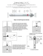
Concrete shall have compression strength of at least 3,000 PSI and a minimum thickness of 4” in order to achieve a
minimum anchor embedment of 3 ¼”. NOTE: When using the standard supplied ¾” x 5 ½” anchors; if the top of
the anchor exceeds 2 ¼” above the floor grade you DO NOT have enough embedment.
Maintain a 6” minimum distance from any slab edge or seam. Hole to hole spacing should be a minimum 6 ½” in
any direction. Hole depth should be a
minimum of 4”.
Do not modify Mechanical Wedge Anchor products. The performance of modified products may be substantially
weakened. Manufacturer will not warrant or guarantee the performance of such modified products.
Do not alter installation procedures from those set forth in this Manual.
Drill holes for mechanical anchors with carbide-tipped drill bits meeting the diameter requirements of ANSI
B212.15 shown in the table below. A properly-sized hole is critical to the performance of mechanical anchors.
Rotary-hammer drills with light, high frequency impact are recommended for drilling holes.
Do not use excessively worn bits or bits which have been incorrectly sharpened.
Please note that the use of oversized holes’ is NOT permitted for anchoring lift. DO NOT USE Anchor Adhesive to
fill spacing of oversize holes’. Move lift location or fill holes with Anchor Adhesive (see manufacturer for proper
curing time) and Re-drill to correct Hole Specification.
Summary of Contents for QJY240C
Page 9: ...9...
Page 23: ...23 Fig 12 Fig 12...
Page 32: ...34 Parts Diagram...
Page 33: ...35 Parts List...
Page 34: ...36 COMPANY INFO BACK PAGE...


