21
Columns
STE P 9:
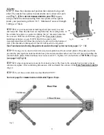
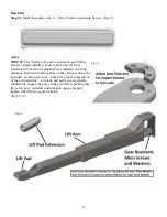
Raise the columns and position the columns facing each
other. The outside base plates measurements are as shown for each
unit
(Fig. 1, 2) for correct measurement to your lift)
. Square
using a chalk line and measuring from rear points on base plates
(mark your positioning within 1/16”). Minimum Concrete Strength
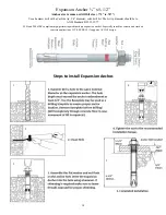
3,000 psi 4” thick.
STE P 10:
Use your measurement markings made previously to center
and locate lift. Once this has been accomplished use the existing holes, in
the column base plate as a guide for drilling the 3/4” diameter holes into
the concrete. Drill the anchor holes only for the Powerside Column,
installing anchors as you go. NOTE: Drill thru concrete slab
(recommended) this will allow the anchor to be driven thru the bottom of
slab, if the threads are damaged or if the lift will need to be relocated.
(See Foundation, Anchoring Requirements and Anchoring Tip Instructions pages 12– 14)
STE P 11:
Using a level, check column for side-to-side plumb and front-to-back plumb. If needed, use shims
provided by placing shims underneath the base plate and around the anchor bolt. This will prevent bending the
column bottom plates (Shim thickness must not exceed 3/8”). Tighten 3/4” anchor bolts to
100 ft-lbs.
of torque.
(see page 14) (Fig 10)
STE P 12:
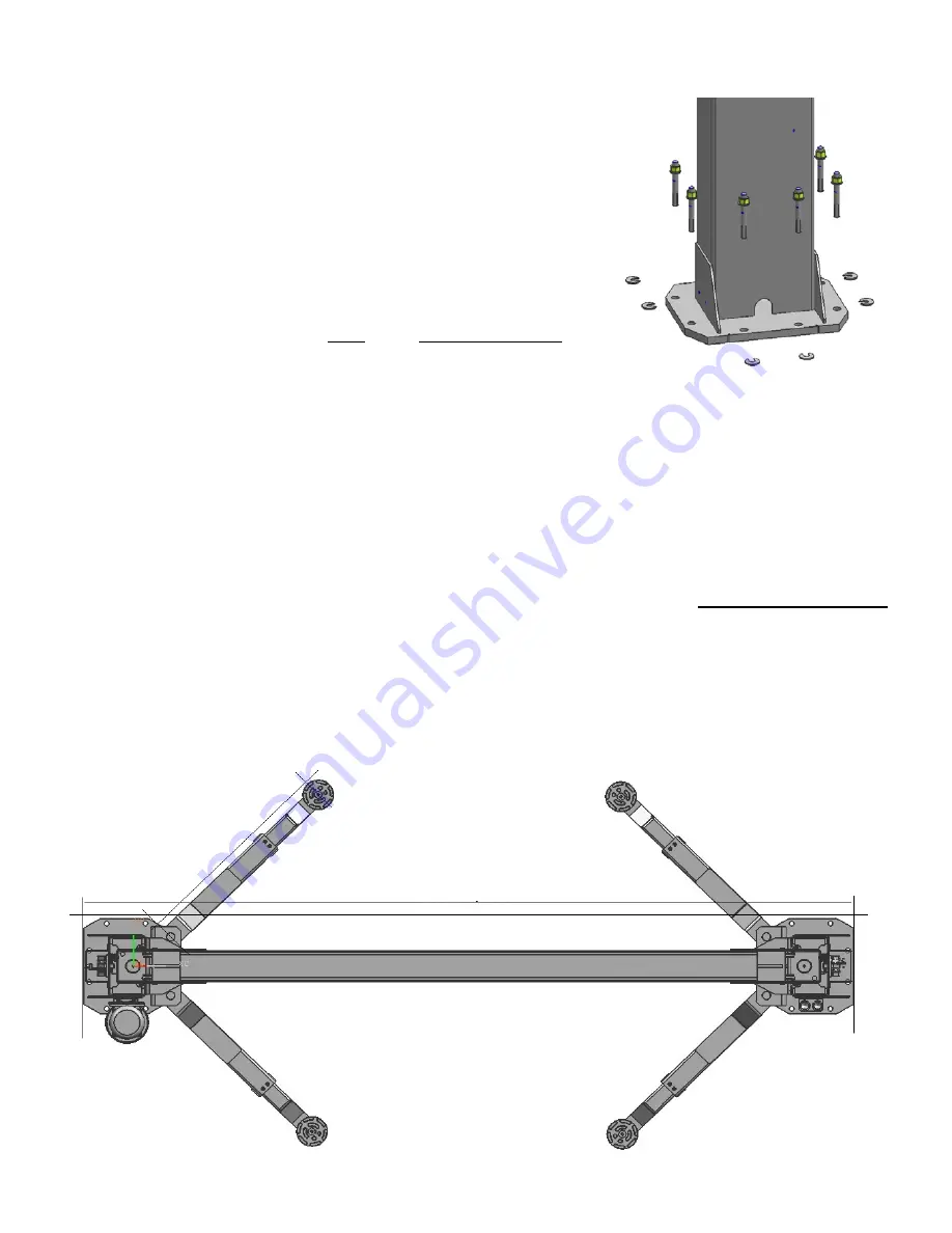
Using a tape measure, measure from back corner of the base to the opposite back corner to insure
columns are square. After confirming dimensions, drill and install the anchors on the
Non-Powerside Column
.
(Fig 11)
STE P 13:
Level the second column as described in STEP 7.
See next page for mea
surements and detailed figures Steps .
Floor Plan
Fig 10
Fig 11
770-1105mm
3319mm/130.6mm
Summary of Contents for QJY240C
Page 9: ...9...
Page 23: ...23 Fig 12 Fig 12...
Page 32: ...34 Parts Diagram...
Page 33: ...35 Parts List...
Page 34: ...36 COMPANY INFO BACK PAGE...

