background image

22 


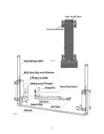
Equalizing Cables 


STEP 14: 

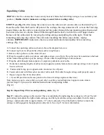
After the columns have been securely fastened. Raise the both lifting carriages to second safety lock 

position.  (

Double check to make sure carriage is secure before routing cable.)  


STEP 15: (see Fig. #2

) After raising the columns route the cables in each column cables as illustrated (Fig #?). 

Route 

the cable from the front tie off point of the carriage, the stop connector will  seat on the front stop 

mount. Make sure the cable is routed up toward the  pulley through the top mounting plate then routed 
back down the rear of column. Route Cable through bottom sheave in direct line with upper sheave. 
Remove all the cable slack by lowering the lifting carriage and pulling the cable tight.  Wind the 
remaining cable into the column. This will make installing the cables easier before  raising           
columns. 

IMPORTANT: 

make sure chain is secured and routed around pulley before lowering 

carriage.(Fig. 12)  


A. Connect the equalizing cables as shown in the cable diagram below on.  
B. Connect top front tie off point first. Route cable to top Sheave. 
C. Remove the top sheave so the cable will seat. 
D. Wrap the equalizer cable over sheave and replace sheave on roll pin. The cable must be routed down the back 
of the column through the top of the carriage.  Route cable through lifting to bottom sheave. 
E. Wrap the cable through bottom sheave. Completely pull slack out of cable. 
F.  Route the remaining lengths of cables around opposite column bottom sheave and up carriage to tie of point

.  

Secure with nut.  

G.   Fasten cable facing up on opposite side column rear tie off point. 
H.  Fasten cable end with flat washer on end of cable until. Pull cable through carriage until properly seated. 
I.  Repeat  steps A thru H for other cable. 
J.  ( if your lift provides and access panel on the front of carriage replace at this time.) 
Note: make sure not to cross cable over each other so cable is routed back down opposite side column. 

(review Step# 12 process for detailed instructions for adjusting cables. 
(Fig 12)


Step 16: Repeat Step 15 for second equalizing  cable. 

(Fig 12) 

 
Step 17: 

Adjust the carriage cable tension. This is accomplished by tightening the carriage tie off nut. The left 

post carriage nut adjusts the right column carriage, and the right column carriage nut adjusts the left column 
carriage. Adjust each cable to approximately 1/2” side-to-side play. Check both safety latches to insure the   
carriage is still engaged in the appropriate safety latch.  See step 15 for more information. 

Summary of Contents for QJY240C

Page 1: ...anual Item T9000 2BP 22 Model QJY240C 2 Post Light Duty Automotive Equipment Lift Symmetric Floor Plate Maximum Lifting Capacity 9 000 lbs PLEASE READ ENTIRE MANUAL PRIOR TO INSTALLATION VERSION 1 10...

Page 2: ...y Carefully inspect the unit on a regular basis and perform all maintenance as required Service and maintain the unit only with authorized or approved replacement parts Keep all instructions permanent...

Page 3: ...escribed in the Installation Instructions section of this manual Failure by the owner to provide the recommended shelter mounting surface electrical supply and ceiling height could result in unsatisfa...

Page 4: ...fect not interfering with equipment functionality or any Incidental indirect or consequential loss damage or expense that may result from any defect failure or malfunction of a product delay in perfor...

Page 5: ...grease and oil spills immediately When the lift is being lowered make sure everyone is standing at least six feet away Be sure there are no jacks tools equipment left under the lift before lowering A...

Page 6: ...l or installation of heavier parts can change the vehicle s center of gravity on the lift resulting in a critical load shift The vehicle may then be unstable Plan ahead for this possibility to insure...

Page 7: ...ed or malfunctioning Only qualified technicians should service the lift Replace damaged components with manufacturer s certified parts 11 Keep the area around the lift clean and free of debris 12 Use...

Page 8: ...ke sure all operators read this manual Manufacturer will assume no liability for loss or damage of any kind expressed or implied resulting from improper installation or use of this product Do not atte...

Page 9: ...9...

Page 10: ...itioning blocking bleeding down etc If this is a lockable device the authorized lockout person places the assigned padlock on the device to prevent its unintentional reactivation An appropriate tag is...

Page 11: ...n a thorough inspection before it is put back into service Factors such as abrasion wear fatigue corrosion improper winding and kinking are often of greater significance in determining if a wire rope...

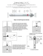
Page 12: ...Anchor Products and must be followed carefully These general instructions are in addition to the specific design and installation instructions and notes provided for each particular product all of wh...

Page 13: ...Place flat washer and hex nut over threaded end of 3 4 x 5 1 2 wedge anchor leaving approximately 1 16 inch of thread exposed carefully tap anchor use a hammer Example A 3 Do not damage threads Tap an...

Page 14: ...se a hammer drill with a Carbide tip 3 4 diameter solid drill bit The bit tip diameter should be to ANSI Standard B95 12 1977 2003 and 2006 IBC compliant high performing medium duty expansion anchor E...

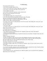
Page 15: ...and or oil foaming up Check that oil used meets the specification in the Installation Instruction section of this manual Tighten all suction line fittings Not enough oil in tank and air has been trans...

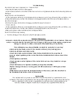
Page 16: ...s in your shop is critical in preventing employee injuries and damage to customer s vehicles Automotive lifts should always be used safely This will help increase the profitability productivity and sa...

Page 17: ...a short chalk line in the area where lift will be located Draw a second chalk line at 90 to locate the positions of both lift columns Refer to lift dimensions on this page Keep thismanualwith lift at...

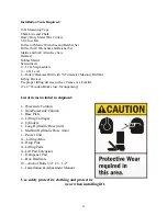
Page 18: ...sonry Drill Bit Lifting Devices Use proper lifting devices such as Cranes or a Forklift 4 x 4 Wooden Blocks use for unpacking List of items included in shipment 1 Powerside Column 1 Non Powerside Colu...

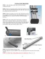
Page 19: ...devices cranes or a forklift to lift off of shipping brackets STEP 4 Slide each carriage 60 70 towards top of columns to expose base of cylinders Open the oil port of each cylinder by unscrewing the b...

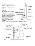
Page 20: ...afety latches There is one safety latch on each lifting carriage Once carriages raise the safety release latch will flip over This will engage the safety lock when lowered To lower lift raise carriage...

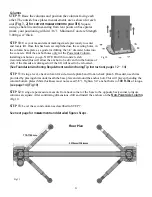
Page 21: ...chor to be driven thru the bottom of slab if the threads are damaged or if the lift will need to be relocated See Foundation Anchoring Requi rements a ndAnchoringTip Instructions pages 12 14 STE P 11...

Page 22: ...ave and replace sheave on roll pin The cable must be routed down the back of the column through the top of the carriage Route cable through lifting to bottom sheave E Wrap the cable through bottom she...

Page 23: ...23 Fig 12 Fig 12...

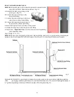
Page 24: ...d F Connect the long hose to the non power side fitting G Secure hose Important Make sure hose does not touch equalizing cable under Base Plate Fig 15 Steps 18 A G STEP 19 Remove the vent plug from th...

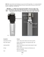
Page 25: ...each circuit with time delay fuse or circuit breaker 208v 230v single phase 60 Hz 20 amp Verify that wiring must comply with local code Description Purpose Safety Release Handle Used to release safet...

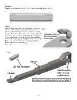
Page 26: ...need to be adjusted once installed on lifting carriages Position the lifting arms on the carriages using the included securing arm pins Check for proper engagement of the arm restraints arm lock and...

Page 27: ...24 Raise lift and LISTEN You will hear the latches begin to hit and release as the lift is being raised After 3 or 4 clicks you will hear the latches synchronizing at the same time If the safety latc...

Page 28: ...matically Post Installation Procedure Verify columns are properly shimmed and plumb Check that expansion anchors are tightened to 100 ft lbs torque Roll pins sheave pins properly attached Lifting carr...

Page 29: ..._______________________________________________________________ ______________________________________________________________________________ _________________________________________________________...

Page 30: ..._______________________________________________________________ ______________________________________________________________________________ _________________________________________________________...

Page 31: ..._______________________________________________________________ ______________________________________________________________________________ _________________________________________________________...

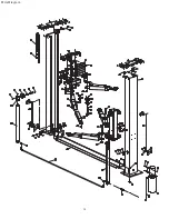
Page 32: ...34 Parts Diagram...

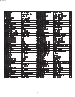
Page 33: ...35 Parts List...

Page 34: ...36 COMPANY INFO BACK PAGE...

Reviews: