30
Donaldson Company, Inc. © 1995
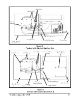
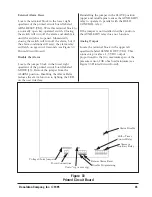
2.6.2 Checker Board Diagnostics and Control
Panel Specifications
See the Installation and Operation Manual for
the Checker Board diagnostic and control panel
for complete information (IOM-72202-00)
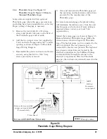
2.6.3 Solid-State Timer Specifications
(See Figure 29 SDF Solid-State Timer
Wiring Diagram)
COMPONENTS:
Standard Downflo model
SDF dust collectors are equipped with 115
volt AC solenoid valves rated at 19.7 watts
each and a solid-state 115 volt AC/50-60Hz/1
timer when ordered.
The timer is factory-adjusted at 100 milliseconds
(1/10 second) pulse time and a 10 second
duration (elapsed time) between pulses.
Input power to the solid-state timer is applied to
L1 and L2 terminals on the timer control circuit
board, which is in parallel with the low voltage
(115/60/1) coil of the blower fan magnetic
starter (see Figure 29 SDF Solid-State Timer
Wiring Diagram). Upon fan start-up, power is
supplied to the control board and the preset OFF
time is initiated. At the end of the OFF time, the
control board timer will energize a
corresponding solenoid valve to provide the ON
time cleaning pulse for one filter element and
then step to the next filter element.
This cycle is continuous unless an auxiliary
control such as a Photohelic pressure switch or a
1TGS toggle switch is used to control the timer
(see Figure 29 SDF Solid-State Timer Wiring
Diagram).
When the
®
is used on the Checker board
diagnostic and control panel, or when the
Photohelic gage is used as an internal control of
the solid-state timer, the valves will pulse only
when the differential pressure reaches the high
set point and will continue the pulse sequence
until the lowest pressure setting is reached (see
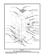
Figure 1 SDF-4 Phantom View and Figure 29
SDF Solid-State Timer Wiring Diagram).
2.6.1 Electrical Operation
All functions on the Downflo model SDF are
controlled from the Checker board diagnostic
and control panel (see Figure 1 SDF-4 Phantom
View).
For starting and operation, refer to the
Installation and Operations Manual for the
Checker board diagnostic and control panel. For
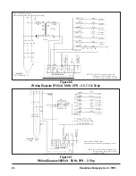
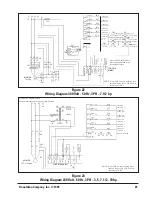
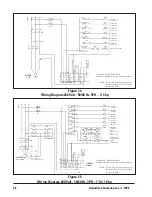
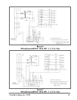
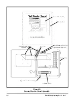
wiring diagrams, see Figures 20, 21, 22, 23, 24,
25, 26, and 27 in this manual.
Each dust collector comes equipped with
solenoid valves that control the pulse cleaning
valves which clean the filter elements. The
solenoids are connected electrically to the
Checker board diagnostic and control panel (see
Figure 1 SDF-4 Phantom View). A wiring
diagram for each size of model SDF is supplied
with the unit.
On versions of the Downsized Downflo without
the Checker board diagnostic and control panel,
the solenoid valves are connected electrically to
the solid-state control timer. A wiring diagram
for each model is supplied with this version.
NOTE
The end user assumes responsibility for
providing all necessary disconnecting
means and overload protection in
accordance with all local codes and
regulations governing this installation.
NOTE
The SDF model solid-state timer requires
a low voltage (105 to 135 volt AC)
control circuit in the fan starter. This is
not supplied by Torit.


