Donaldson Company, Inc. © 1995
35
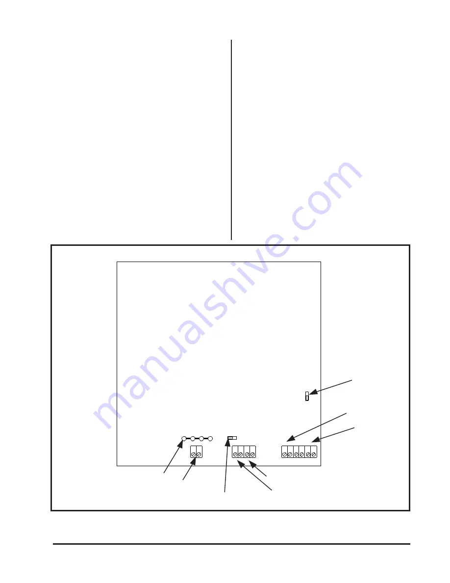
External Alarm Reset
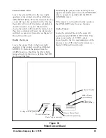
Locate the terminal block in the lower right
quadrant of the printed circuit board labeled
ARM. RESET (TB2). Wire this terminal block to
a normally open key-operated switch. Closing
the switch will turn off the alarm and disable it
until the switch is reopened. Momentarily
closing the switch will turn off the alarm, but if
the alarm conditions still exist, the alarm relay
will latch on again in 10 seconds (see Figure 33
Printed Circuit Board).
Disable the Alarm
Locate the jumper block in the lower right
quadrant of the printed circuit board labeled
MODE (J5). Remove the jumper from the
ALARM position. Disabling the Alarm Relay
reduces the alarm function to lighting the LED
on the user interface.
Reinstalling the jumper in the SLAVE position
(upper and middle pins) causes the AUXILIARY
relay to operate in parallel with the HI/LO
CONTROL relay.
If the jumper is not installed in either position,
the AUXILIARY relay does not function.
Analog Output
Locate the terminal block in the upper left
quadrant labeled SENSOR OUT (TB4). This
connector provides a 1-5 VDC output
proportional to the 0 to maximum span of the
pressure sensor, 10K ohm load minimum (see
Figure 33 Printed Circuit Board).
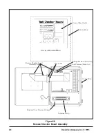
Figure 33
Printed Circuit Board
Alarm Disable
Alarm or
Auxiliary Relay
Hi/Lo Timer
Control Relay
{
{
{ {
Remote Alarm Reset
Disable Programming
Units ("wg or mm wg)
Power Connections
Voltage Choice Jumpers

