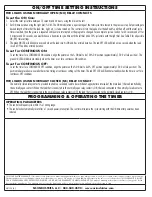
ON/OFF TIME SETTING INSTRUCTIONS
FOR LOADS USING NORMALLY OPEN (NO) RELAY CONTACTS
To set the ON time:
1. Select the total cycle time between 15 seconds and 24 hours, using the dial on the left.
2. Set ON time duration using the right dial (% ON). The ON time duration is a percentage of the total cycle time chosen in the previous step. Set percentage to
desired length of time that the load (fan, light, etc,) is to be turned on. The control will turn the load on for the defined % and then off until the total cycle
time is reached, then the process is repeated until power is interrupted or the program is changed. For example to cycle a load on for 30 seconds and off for
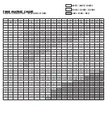
4 minutes and 30 seconds, one would choose a five minute cycle time with the left dial and a 10% cycle time with the right dial. See Table 2 for all possible
ON/OFF time settings.
3. The green ON LED will blink once a second when the load circuit is ON and has a timed duration. The red OFF LED will blink once a second when the load
circuit is OFF and has a timed duration.
To set for CONTINOUS ON:
To set the timer for a CONTINUOUS ON condition, align the pointer on the % ON dial to be 100% ON position (approximately 12:00 o’clock position). The
green ON LED will illuminate steadily when the timer is set for a continuous ON condition.
To set for CONTINOUS OFF:
To set the timer for a CONTINUOUS OFF condition, align the pointer on the % ON dial to be 0% OFF position (approximately 12:00 o’clock position.) This
position takes precedence over all other active timing or continuous settings of the timer. The red OFF LED will illuminate steadily when the timer is set for a
continuous OFF conditions.
FOR LOADS USING NORMALLY CLOSED (NC) RELAY CONTACT:
The normally closed relay contact is provided to enable a secondary load to be switched at opposite time intervals of the main load (the load controlled by
the normally open contact.) When the load that is connected to the normally open relay contact is ON, the load connected to the normally closed contact is
OFF. When the load that is connected to the normally open relay contact is OFF, the load that is connected to the normally closed contact is ON.
PROGRAMMING & OPERATING THE TIMER
OPERATING PARAMETERS
•
The control will repeat cycle within 1% of timing range.
•
The control will automatically reset after a 1 second power interruption. The control will resume the cycle starting with the ON time after power has been
restored.
ONE YEAR LIMITED WARRANTY: If this product fails because of a manufacturing defect within one year after purchase, we will, at our option, either repair or replace it at no charge.
Our warranty does not cover damage caused by accident, abuse or misuse. We assume no further liability with respect to the sale or use of this product. THIS WARRANTY IS IN LIEU
OF ALL OTHER WARRANTIES, EXPRESSED OR IMPLIED, INCLUDING THE WARRANTY OF MERCHANTABILITY. We make no warranty with respect to the fitness of any goods for the
users particular appplication. This warranty gives you specific legal rights, and you also may have other rights which vary from state to state.
MLI-194(B)
NSI INDUSTRIES, LLC • 888.500.4598 • www.nsiindutries.com


