background image

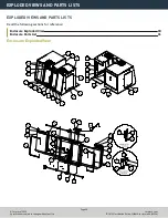
EXPLODED VIEWS AND PARTS LISTS
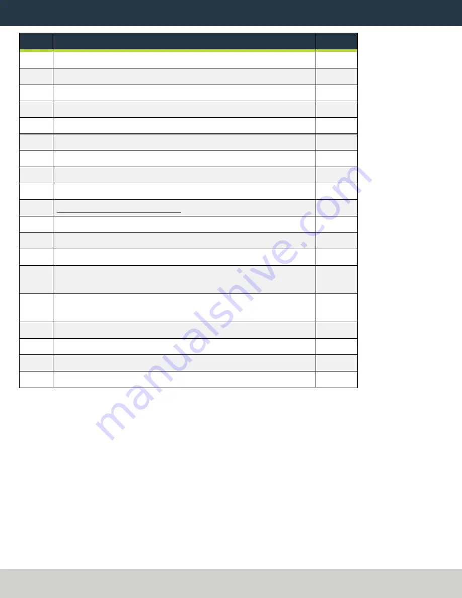
ID

Description

Quantity

29

Door Bumper (PN 38357)

8

30

Handle, 400 mm (PN 37611)

2

31

Door Seal (PN 37644)

2

32

Enclosure Ball Latch, Female (PN 38482)

1

33

Enclosure Ball Latch, Male (PN 38483)

1

34

Washer, Flat, M5, Stainless Steel (PN 37939)

2

35

Nut Bar (PN 37585)

1

36

Switch Key Bracket (PN 37586)

1

37

Locking Door Switch Installation/Cover Plate (PN 38272)

1

38

Door Lock Switch Kit (PN 38283)

1

39

Cable Tie Anchor, Screw Mount, M5 (PN 31460)

3

40

Round Plug, 32 mm (PN 37598)

3

41

Sealing Strip, Rubber (PN 38356)

21

42

Screw, Button Head Cap (Flanged), M6 × 1 - 12, Stainless Steel (PN
38206)

76

43

Screw, Button Head Cap (Flanged), M5 × 0.8 - 10, Stainless Steel (PN
38205)

151

44

Screw, Socket Head Cap, M5 × 0.8 - 20 (PN 30357)

8

45

Screw, Socket Head Cap, M8 × 1.25 - 22 (PN 37190)

4

46

Washer, Flat, M8 (PN 30531)

4

47

Decal, Enclosure, 1100MX, Front Left Panel (PN 39032)

1

Page 32

©Tormach® 2022
Specifications subject to change without notice.

tormach.com

TD10711: Installation Guide: 1100MX Enclosure Kit (0522A)

Summary of Contents for 1100MX

Page 1: ...Page 1 Specifications subject to change without notice Tormach 2022 TECHNICAL DOCUMENT Version 0522A INSTALLATION GUIDE 1100MX ENCLOSURE KIT...

Page 2: ...rt ticket with Tormach Technical Support at tormach atlassian net servicedesk for guidance on how to proceed 2 Read the packing list and locate all items During the installation remove labels from the...

Page 3: ...RED TOOLS l Metric hex wrench set l Permanent marker l Shears or knife Page 3 Tormach 2022 Specifications subject to change without notice tormach com TD10711 Installation Guide 1100MX Enclosure Kit 0...

Page 4: ...nstall the side windows until later in the procedure Keep all screws one quarter turn loose while installing the enclosure panels This makes aligning panels easier Once you re done installing the encl...

Page 5: ...igure 2 Left side panel attached to the left rear panel 2 Attach the left side panel to the left chip pan with five M6 1 0 12 screws Figure 3 Left side panel attached to the left chip pan Page 5 Torma...

Page 6: ...tall two vertical window retainers on both sides of the left side panel s window opening with two sets of three M5 0 8 10 screws Don t fully tighten the screws Leaving the window retainers loose makes...

Page 7: ...e 5 Left front panel attached to the left chip pan 2 Attach the left front panel to the left side panel with eight M5 0 8 10 screws Figure 6 Left front panel attached to the left side panel Page 7 Tor...

Page 8: ...e enclosure splice plate with four M5 0 8 10 screws 2 Attach the right side panel to the right chip pan with four M6 1 0 12 screws Install the Right Side Window Retainers Note To make it easier to ins...

Page 9: ...de window retainers attached to the right side panel Install the Right Front Panel 1 Attach the right front panel to the right chip pan with two M6 1 0 12 screws Figure 8 Right front panel attached to...

Page 10: ...t side panel Install the Left Top Panel 1 Attach the left top panel to the panels on the left side of the enclosure with 12 M5 0 8 10 screws Figure 10 Left top panel attached to the left side of the e...

Page 11: ...rs Install the Right Top Panel 1 Attach the right top panel to the panels on the right side of the enclosure with nine M5 0 8 10 screws Figure 12 Right top panel attached to the right side of the encl...

Page 12: ...right top panels connected 3 Attach three cable tie anchors to the right top panel with three M5 0 8 10 screws Figure 14 Location to attach three cable tie anchors Page 12 Tormach 2022 Specifications...

Page 13: ...screws Figure 15 Front upper panel attached to the right and left front panels 2 Attach the front upper panel to the right and left top panels with four M5 0 8 10 screws Figure 16 Front upper panel at...

Page 14: ...h the front lower panel to the right and left chip pans with four M5 0 8 10 screws Figure 18 Front lower panel attached to the right and left chip pans Install the Rear Splash Shield Attach the rear s...

Page 15: ...mping screws b Slide one bumper onto the linear rail c Slide two linear bearings onto the linear rail d Slide one bumper onto the opposite end of the linear rail e Slide one linear rail mount onto the...

Page 16: ...bly to the outside of both the right front panel and the front lower panel with two sets of two M6 1 0 12 screws Figure 21 Right lower linear assembly attached to the outside of the enclosure s lower...

Page 17: ...screws face in the following directions l Up on the lower linear assemblies l Down on the upper linear assemblies Figure 22 Four linear assemblies attached to the enclosure Page 17 Tormach 2022 Speci...

Page 18: ...ound the perimeter of the window and ends at the opposite side of the door handle mount When finished use shears or a knife to cut the excess trim 2 Remove and discard the protective plastic film from...

Page 19: ...g front door Install the Front Door Assemblies Each front door is attached to the enclosure by securing it to the linear bearings the wider door is mounted on the left side of the enclosure and the na...

Page 20: ...he two bottom linear bearings with two sets of four M5 0 8 10 screws 3 Repeat Steps 1 to 2 to attach the wide door to the top and bottom linear rail assemblies on the remaining side of the enclosure F...

Page 21: ...tep 4 for the remaining front door 6 Attach the handles to both front doors with two sets of two M8 x 1 25 20 screws and two sets of two M8 flat washers Figure 28 Both front door handles attached to t...

Page 22: ...pin on the three prong connector and the floodlight s bracket screw b Read the OHMS value that displays The value should be less than 5 OHMS If the value is greater than 5 OHMS don t install the flood...

Page 23: ...1 to 3 to install the floodlight on the left side 5 Connect the short power cable from the Enclosure Cable Kit to the plug on the right floodlight 6 Connect the long power cable from the Enclosure Cab...

Page 24: ...f rubber trim to the edge of the window opening on each side panel Verify that the trim covers the entire perimeter of the window When finished use shears or a knife to cut the excess trim Figure 31 R...

Page 25: ...sliding into the window opening 4 Push a strip of rubber trim onto the edge of one horizontal window retainer When finished use shears or a knife to cut the excess trim 5 Attach one horizontal window...

Page 26: ...e round hole plugs into the three holes on the left rear panel Figure 34 Round hole plugs pushed into the left rear panel 2 Push a strip of rubber trim to the edge of the access panel opening on the l...

Page 27: ...l the remaining fasteners Figure 35 Supporting screw inside the left rear panel 4 Tilt the access panel and put it through the opening on the left rear panel Then hang it inside the enclosure on the i...

Page 28: ...nel Install the Stainless Steel Wear Guard Find the stainless steel wear guard that you set aside earlier Attach it to the lower front panel with two M5 0 8 10 screws Figure 38 Stainless steel wear gu...

Page 29: ...abel with a permanent marker You have completed assembling and installing the 1100M Enclosure Replace the Windows When required replace the windows with the following parts l Window 1100 Side PN 37648...

Page 30: ...ISTS Read the following sections for reference Enclosure Exploded View 30 Enclosure Parts List 31 Enclosure Exploded View Page 30 Tormach 2022 Specifications subject to change without notice tormach c...

Page 31: ...Rear PN 37639 1 13 Enclosure Panel 1100 Splash Shield PN 38691 1 14 Enclosure Panel 1100 Splice Plate PN 38695 1 15 Enclosure Panel 1100 Column Splice PN 37663 1 16 Enclosure Door 1100 Right PN 37640...

Page 32: ...Switch Kit PN 38283 1 39 Cable Tie Anchor Screw Mount M5 PN 31460 3 40 Round Plug 32 mm PN 37598 3 41 Sealing Strip Rubber PN 38356 21 42 Screw Button Head Cap Flanged M6 1 12 Stainless Steel PN 38206...

Reviews: