


Tormach, Inc.
P: 608.849.8381 / F: 209.885.4534
tormach.com
TECHNICAL DOCUMENT
Page 10
©Tormach® 2020. All rights reserved.
Specifications subject to change without notice.
TD10487_PCNC440_ATC_Install_1220A
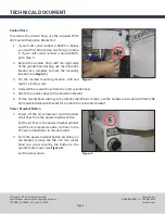
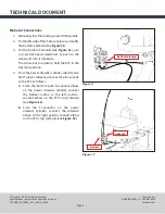
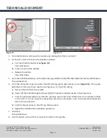
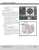
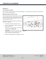
2.
From the front of the machine, make sure the motor enclosure is approximately 1/8 inch from the mill’s
spindle head (see
Figure 14
). If it is not:
a.
On the adjustable standoffs, use an adjustable wrench to loosen or tighten the nut.
b.
Move the ATC assembly in the X direction.
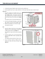
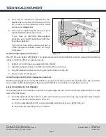
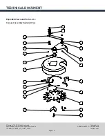
3. On the tilt standoff, use an adjustable wrench to turn the nut until the front side of the motor enclosure
is approximately parallel with the mill’s spindle head (see
Figure 15
).
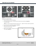
4.
From the four standoffs, securely tighten four
flange nuts.
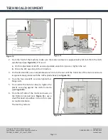
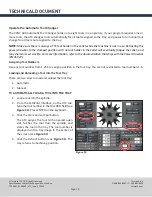
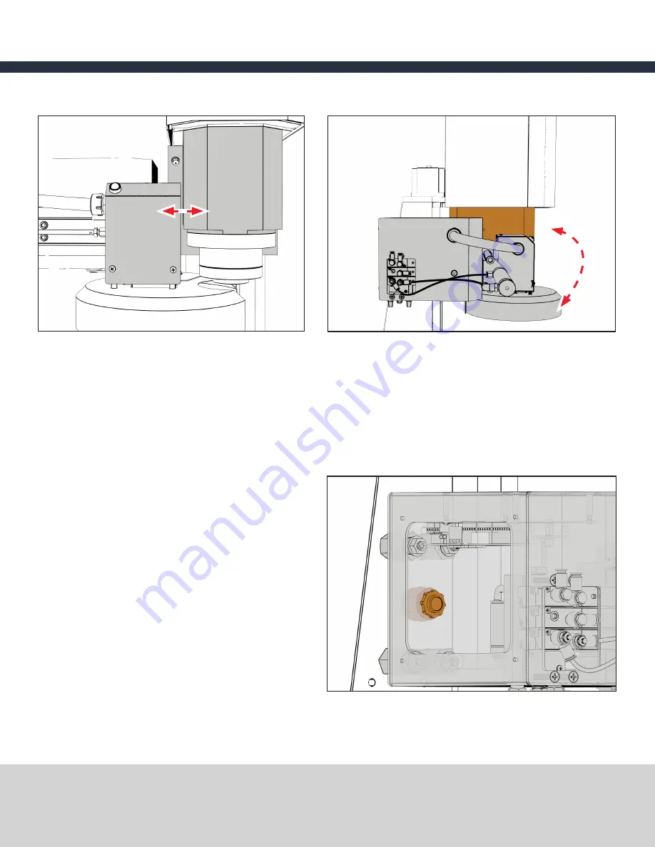
5. From inside the motor enclosure, tighten the
plastic wire plug against the mill’s Z-column
(see
Figure 16
).
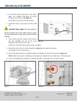
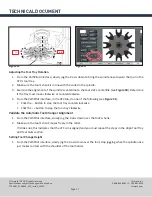
6. From the left side of the motor enclosure, on
the Bottom Solenoid (see
Figure 11
), use a
small flat-head screwdriver to turn the screw
on counterclockwise.
The tool tray retracts.
Figure 15
Figure 16
Figure 14


