

Tormach, Inc.
P: 608.849.8381 / F: 209.885.4534
tormach.com
TECHNICAL DOCUMENT
Page 13
©Tormach® 2020. All rights reserved.
Specifications subject to change without notice.
TD10487_PCNC440_ATC_Install_1220A
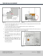
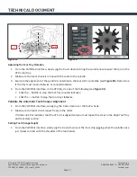
3.
From the
Main
tab, reference the machine by clicking
Ref Z
,
Ref X
, and
Ref Y
.
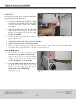
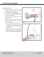
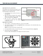
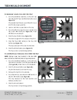
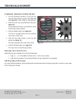
4.
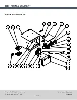
On the ATC, insert a tool into the spindle as follows:
a.
Push and hold the button (see
Figure 19
).
The collet opens.
b.
Insert a tool into the spindle.
c.
Release the button.
The collet closes.
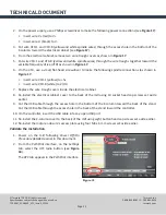
5. From the PathPilot interface, on the
Main
tab, type
1000
into the
RPM
DRO field and click the
FWD
button.
The spindle starts.
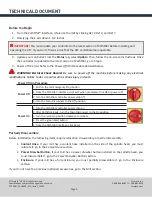
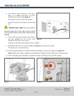
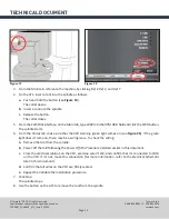
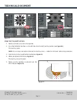
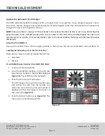
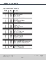
6.
From the
Status
tab, make sure that the
VFD Running
green light comes on (see
Figure 20
). If the green
light doesn’t come on, there may be a wiring issue. To check the wiring:
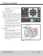
a.
Remove the tool from the spindle.
b.
Power off the mill following the
Power Off/On Procedure
detailed earlier in this document.
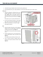
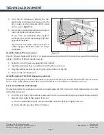
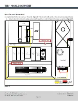
c.
From the electrical cabinet, on the VFD, examine wire VFD-8, and confirm that it’s connected to 2/HA
on the VFD. If it’s not, make this connection (for more information, refer to the
Electrical Schematic
later in this document).
d.
Confirm that all wires on the VFD are firmly seated.
e.
Repeat the
Validate the Installation
procedure.
7.
Click
Stop
.
The spindle stops.
8.
Use the button on the ATC to remove the tool from the spindle.
Figure 20
Figure 19


