Tormach, Inc.
P: 608.849.8381 / F: 209.885.4534
tormach.com
TECHNICAL DOCUMENT
Page 15
©Tormach® 2020. All rights reserved.
Specifications subject to change without notice.
TD10487_PCNC440_ATC_Install_1220A
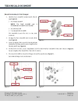
Adjusting the Tool Tray Load Position
If the spindle is not centered over the fork in the X
direction, you must manually adjust the position of
the ATC assembly on the linear rails.
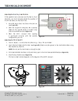
1.
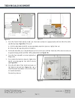
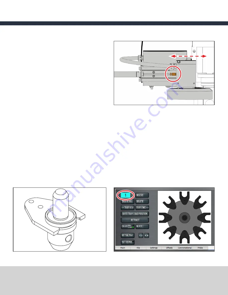
From the ATC’s linear rail, loosen the jam nut
(see
Figure 24
).
2.
Slide the coupler to bring the ATC assembly
closer to the spindle head or further away
from the spindle head (see
Figure 24
).
3. After the ATC’s carousel door opening
is positioned correctly with the spindle,
re-tighten the jam nut.
Adjusting the Tilt of the ATC
1.
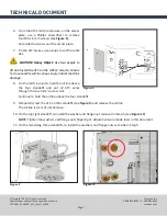
Insert a dowel — no more than 8 inches long — into a TTS tool holder.
2.
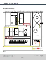
Insert the tool holder into the fork (see
Figure 25
). Make sure the groove in the tool holder slides along
the shoulder on the fork.
NOTE:
Do not rest the tool holder on top of the fork.
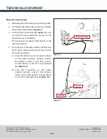
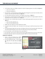
3. From the PathPilot interface, on the
ATC
tab, type
1
in the
Tool Number
DRO field (see
Figure 26
).
4.
Click the
Insert
button (see
Figure 26
).
The tool number entered appears on the diagram of the ATC’S carousel.
Figure 26
Figure 24
Figure 25


