background image

Tormach, Inc.

P: 608.849.8381 / F: 209.885.4534

tormach.com

TECHNICAL DOCUMENT

Page 17

©Tormach® 2020. All rights reserved.

Specifications subject to change without notice.

TD10487_PCNC440_ATC_Install_1220A

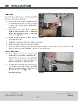
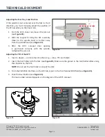
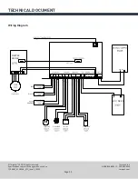
Adjusting the Tool Tray Rotation

1. 

From the PathPilot interface, slowly jog the Z-axis down to bring the spindle nose toward the tool in the 

ATC’s tool tray.

2. 

Make sure the tool’s shank is in line with the collet in the spindle.

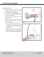
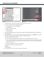
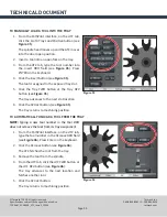
3.  Examine the alignment of the spindle’s centerline to the tool slot’s centerline (see 

Figure 30

). Determine 

if the tray must move clockwise or counterclockwise.
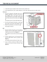
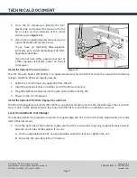
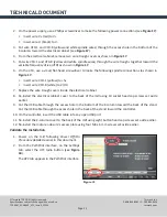
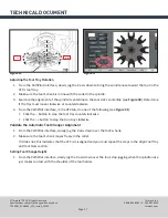
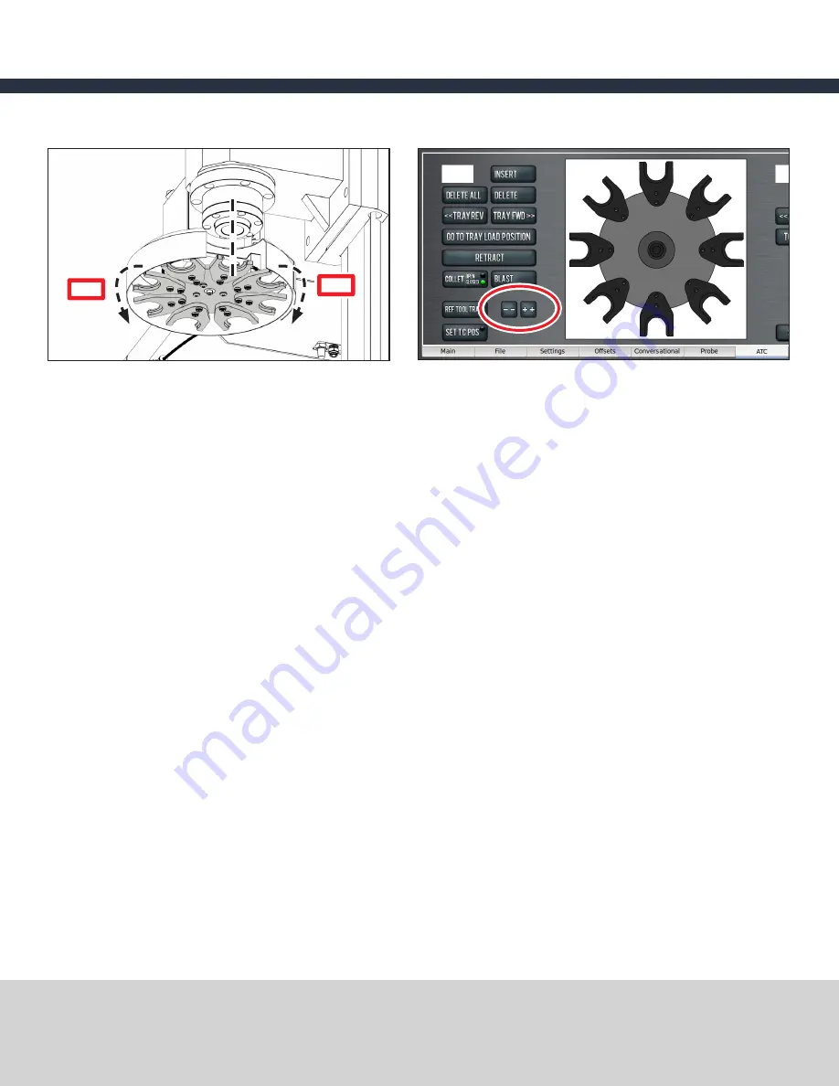
4. 

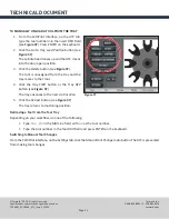
From the PathPilot interface, in the 

ATC

 tab, do one of the following (see 

Figure 31

):

• 

Click the 

-- 

button to step the tool tray counterclockwise

• 

Click the 

++ 

button to step the tool tray clockwise

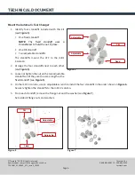
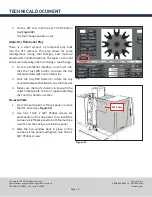
Validate the Automatic Tool Changer Alignment

1. 

From the PathPilot interface, slowly jog the Z-axis down over the tool’s shank.

2. 

Make sure the tool’s shank moves freely in the collet.
If it does not, this indicates that the ATC is misaligned and you must repeat the steps in the 

Align Tool Tray 

and Tool Slots 

section.

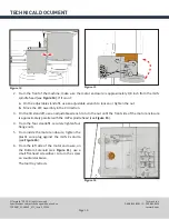
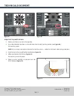
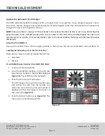
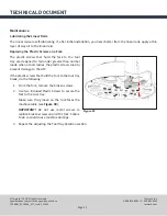
Setting Tool Change Height

1. 

From the PathPilot interface, slowly jog the Z-axis down over the tool; stop jogging when the spindle nose 

just makes contact with the shoulder of the tool holder.

Figure 31 

Figure 30 

--

++

Summary of Contents for PCNC 440

Page 1: ...t 37260 10 Plastic Screw 32173 1 Tilt Standoff Assembly 35911 NOTE If any of these items are missing contact Tormach Customer Service at 608 849 8381 for a replacement IMPORTANT Please read this secti...

Page 2: ...the PCNC 440 Power Drawbar on your machine before installing the PCNC 440 Automatic Tool Changer ATC Do not install the power drawbar button tool changes are completed with the ATC Small flat head sc...

Page 3: ...serious injury or death Power Off On Procedure Power Off 1 Push in the red Emergency Stop button 2 From the PathPilot interface click Exit when prompted click OK to power off 3 Turn the PathPilot con...

Page 4: ...igure 1 3 On the marked mounting location drill and tap for a 6 mm screw 4 Uninstall the coolant hose from the mill s spindle head 5 Attach the coolant hose to the relocation bracket 6 On the spindle...

Page 5: ...ne column and the left side panel of the enclosure see Figure 3 Set aside the screws and the Left Back Panel 2 From the enclosure s top panel on the three gibs loosen nine 10 32 x 3 8 Phillips screws...

Page 6: ...e standoffs The standoffs mount the ATC to the mill s Z column 2 Arrange the four standoffs next to each other see Figure 5 3 Loosenortightenthenutonthetwoadjustable standoffs until they are the same...

Page 7: ...column Failure to do so could result in serious injury and or machine damage 8 On the mill s Z column hold the oil line above the four standoffs and put all ATC wires through the Z column s access sl...

Page 8: ...river to push in the screw and turn it clockwise The screw locks in place to hold the ATC in the tray load position 4 From the power drawbar cylinder identify two 5 32 plastic tubes and connect the lo...

Page 9: ...ing a condition of low air supply pressure 1 Splice the 1 4 inch main air supply line from the ATC 2 Insert the spliced air lines into either end of the Pressure Sensor 3 Plug the electrical connector...

Page 10: ...tighten the nut b Move the ATC assembly in the X direction 3 On the tilt standoff use an adjustable wrench to turn the nut until the front side of the motor enclosure is approximately parallel with th...

Page 11: ...Figure 17 The steps to follow detail the connections shown below 1 Put wire V and V red and black power wires through the Z column toward the power supply see Figure 17 Fuse 3 Wire Trough Wire Trough...

Page 12: ...spindle connections as shown in Figure 17 Insert wire VFD 1 yellow to 5v Insert wire VFD 8 white to 2 HA 7 Replace the wire trough covers inside the electrical cabinet 8 Re install the electrical cabi...

Page 13: ...on The spindle starts 6 From the Status tab make sure that the VFD Running green light comes on see Figure 20 If the green light doesn t come on there may be a wiring issue To check the wiring a Remov...

Page 14: ...l in the spindle 2 From the PathPilot interface on the ATC tab click the Ref Tool Tray button see Figure 21 The tool tray spins NOTE You are only required to reference the tool tray once unlike the mi...

Page 15: ...to the spindle head or further away from the spindle head see Figure 24 3 After the ATC s carousel door opening is positioned correctly with the spindle re tighten the jam nut Adjusting the Tilt of th...

Page 16: ...rail loosen two 5 mm socket head cap screws see Figure 28 and slowly pivot the ATC assembly until the dowel is parallel with the 1 2 3 block re tighten 5 mm socket head cap screws b Re check the alig...

Page 17: ...ove clockwise or counterclockwise 4 From the PathPilot interface in the ATC tab do one of the following see Figure 31 Click the button to step the tool tray counterclockwise Click the button to step t...

Page 18: ...nge 1 From the PathPilot interface on the ATC tab click the Tray FWD button to rotate the tray clockwise forward one full tool slot 2 Click the Tray REV button to rotate the tray counterclockwise back...

Page 19: ...nd may shorten its service life For more information refer to the documentation that ships with the Power Drawbar PN 35927 Assigning Tool Numbers Use any tool number from 1 256 to assign a position in...

Page 20: ...he exposed tray slot 5 Click the Tray FWD button or the Tray REV button see Figure 35 The tray advances to the next slot location 6 Click the Retract button see Figure 35 The tray returns to machining...

Page 21: ...3 Click the Delete button see Figure 37 The tool is unassigned from the tray and the tray moves to that tool 4 Click the Tray FWD button or the Tray REV button see Figure 37 The tray advances to the n...

Page 22: ...rk The plastic screws that hold the fork to the tool tray are designed to fail under greater than normal loads when a tool crashes the plastic screws snap to prevent damage to the ATC If the plastic s...

Page 23: ...NICAL DOCUMENT Page 23 Tormach 2020 All rights reserved Specifications subject to change without notice TD10487_PCNC440_ATC_Install_1220A Exploded Views and Parts Lists Carousel Assembly Exploded View...

Page 24: ...Nylon Standoff 4 35838 Blaster Tee Mount 5 35918 5 32 Air Blast Hose 6 35839 5 32 Tee 7 35842 M4 12mm Pan 8 35841 Blaster Guide 9 35889 M4 Hex Nut 10 32133 Tray Arm Pin Front 11 35919 Lever Arm Beari...

Page 25: ...NICAL DOCUMENT Page 25 Tormach 2020 All rights reserved Specifications subject to change without notice TD10487_PCNC440_ATC_Install_1220A Motor and Actuator Exploded View 26 24 1 19 15 16 13 14 11 28...

Page 26: ...Socket Head Cap Screw 11 35858 16 mm Rail 12 35859 16 mm Shuttle 13 35860 Cylinder Mounting Plate 14 35881 Magnetized Shuttle 15 35861 M10 10 mm Socket Head Cap Screw 16 35863 5 32 1 8 NPT Male Conne...

Page 27: ...ach com TECHNICAL DOCUMENT Page 27 Tormach 2020 All rights reserved Specifications subject to change without notice TD10487_PCNC440_ATC_Install_1220A Mount and Control Exploded View 11 10 27 5 21 22 2...

Page 28: ...5 32 1 8 NPT Elbow 10 35887 5 32 1 8 NPT Male Connector 11 35888 Muffler 12 32226 Check Valve In Line 13 32169 10 32 1 4 Push Connector 14 35890 1 4 NPT Hex Plug 15 35891 Air Isolator Baffle 16 35892...

Page 29: ...ormach 2020 All rights reserved Specifications subject to change without notice TD10487_PCNC440_ATC_Install_1220A Wiring Diagram V GND VDC IN INDEX CYL BLDC DRIVE TRAYBLSTPDB AUX PRS PNDPDL STEPPER DR...

Reviews: