Tormach, Inc.
P: 608.849.8381 / F: 209.885.4534
tormach.com
TECHNICAL DOCUMENT
Page 5
©Tormach® 2020. All rights reserved.
Specifications subject to change without notice.
TD10487_PCNC440_ATC_Install_1220A
3. Uninstall the power drawbar button from the mill’s spindle head.
4.
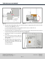
On the spindle motor cover, replace the M6 x 12 mm socket head cap screw set aside in Step 2.
Enclosure
1.
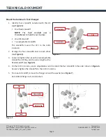
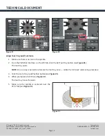
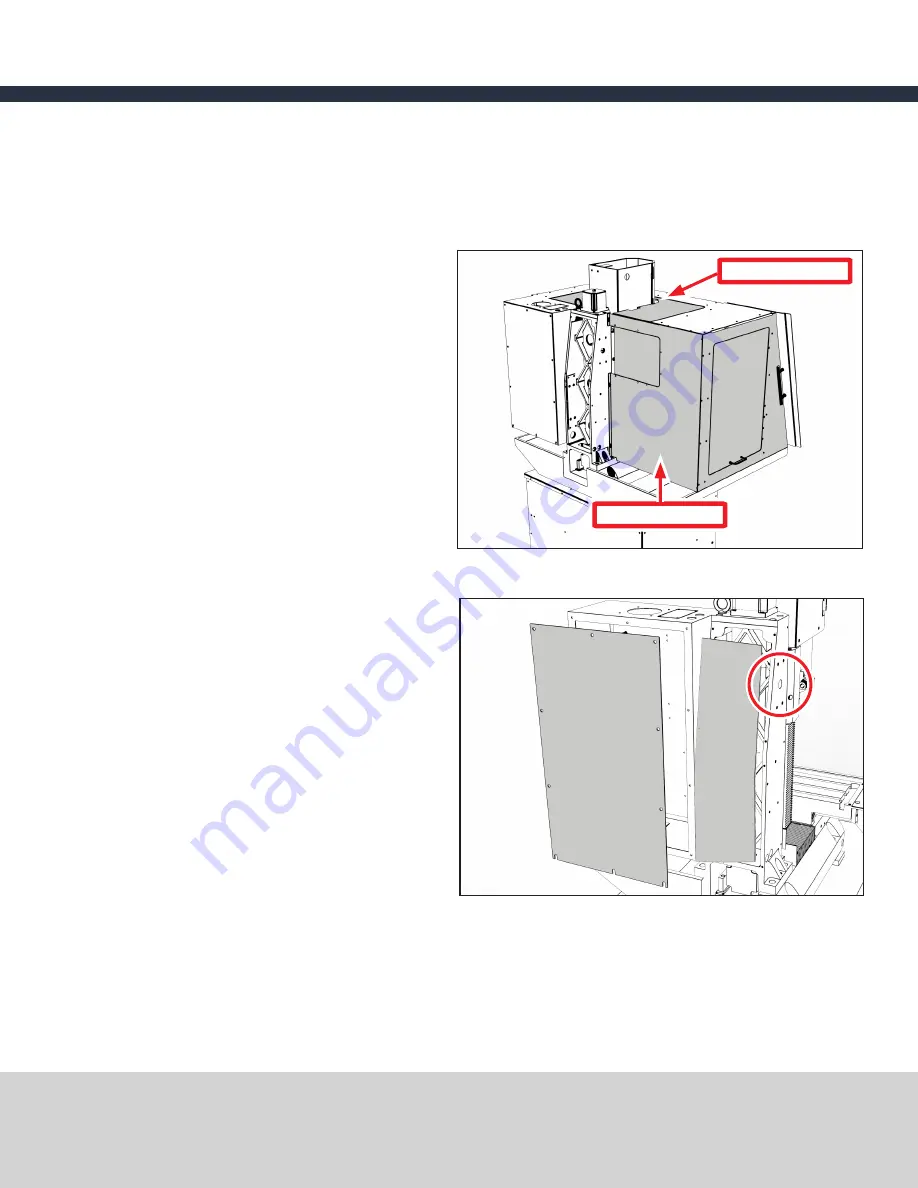
From the enclosure’s Left Back Panel, use a
Phillips screwdriver to remove nine 10-32 x
3/8” Phillips screws. The screws secure the
Left Back Panel to the machine column and
the left side panel of the enclosure (see
Figure
3
).
Set aside the screws and the Left Back Panel.
2.
From the enclosure’s top panel, on the three
gibs, loosen nine 10-32 x 3/8” Phillips screws.
3. Slide the Top Window out of the three gibs.
Set aside the window.
Mill
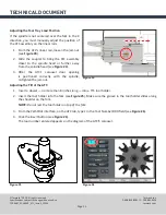
1.
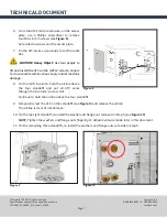
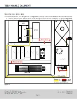
From the back of the mill, on the electrical
cabinet, use a 3 mm hex wrench to remove 10
socket head cap screws (see
Figure 4
).
Set aside the screws and the electrical cabinet
cover.
2.
On the Z-column, use a 3 mm hex wrench to
remove eight button head cap screws (see
Figure 4
).
Set aside the screws and the Z-column cover.
3. Use a 4 mm hex wrench to remove four set
screws from the side of the Z-column (see
Figure 4
).
Figure 4
Figure 3
Left Back Panel
Top Window


