PowerSlide 24
ENGLISH
4 7
8
7.5 DIRECTION OF MOVEMENT CHECK
RISKS
PERSONAL PROTECTIVE EQUIPMENT
F
Disconnect power to the system before making connections
L
i
The operations described in this section are essential for the proper
operation of the gear motor.
1. Move the gate manually to its half-travel position and restore
automatic operation (§ ).
2. Make sure that both the FCC and FCA LEDs are lit.
3. Check that the magnetic limit switches are in the correct position
(§ ).
4. Check that the
dI
function in Basic Programming (§ -
) is set
correctly.
5. Turn the electronic board off and on again using the circuit breaker.
6. Open the gate (OPEN A); check that the gate actually performs an
opening movement in correspondence with the status indicator
01
on the display.
7. If it doesn’t, invert the two electric motor phase wires: J6, terminals
14 and 15 (§ -
). Repeat the operations indicated in points 5 and 6.
8. Check that the gate stops automatically when both limit switches
are tripped. In particular:
-
the display must indicate status
03
or
04
in correspondence with
the opening limit switch.
-
the display must indicate status
00
in correspondence with the
closing limit switch.
7.6 FINAL OPERATIONS
RISKS
PERSONAL PROTECTIVE EQUIPMENT
1. Ensure that the forces generated by the leaf are within the limits
allowed by the standard. Use an impact curve gauge in ac-
cordance with standards EN 12453 and EN 12445. For countries
outside the EU, when there is no specific local standard, the force
must be less than 150 N static.
2. Ensure that the maximum manual moving force of the leaf is less
than 225 N.
3. Use appropriate signs to highlight the areas where residual risks
remain despite having implemented all safety measures.
4. Put up the ‘’DANGER: AUTOMATIC MOVEMENT’’ sign on the gate
in a visible position.
5. Put up the CE marking on the gate.
6. Complete the EC Declaration of Conformity of the machine and
the system Logbook.
7. Provide the owner/operator of the automation with the EC Decla-
ration, the system Logbook with the maintenance schedule and
the user instructions of the automation.
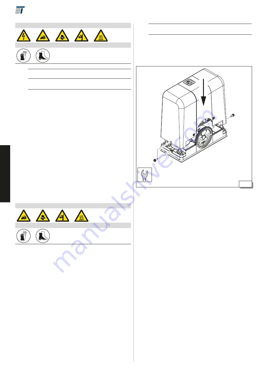
INSTALLING THE CASING
!
Mount the casing following the instructions in
4 7
: choose between
the hexagonal insert screws and the Allen screws provided, size M5.
Summary of Contents for POWERSLIDE
Page 1: ...POWERSLIDE GEBRAUCHSANLEITUNG D 913002 26 6 50 01 2018...
Page 2: ......
Page 31: ...POWERSLIDE INSTRUCTION MANUAL GB...
Page 32: ......
Page 61: ...POWERSLIDE GEBRUIKSAANWIJZING NL...
Page 62: ......
Page 91: ...PowerSlide 31...


