background image

78 - NL

T100 R

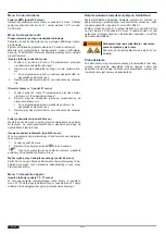
Verlichting en / of voorwaarschuwingslamp (optioneel)

De  besturing  heeft  2  relaisuitgangen,  waarmee  de  verlichting  of
een  voorwaarschuwingslamp  kan  worden  geschakeld  (menu-
punt 45 en 46).

Externe commandotoestellen / pulsgevers (optioneel)

De deur kan door externe commandotoestellen / pulsgevers wor-
den geopend en gesloten.

Draadloze handzender (optioneel)

De bedrijfsmodus van de draadloze handzender kan via menu 6
bij menupunt 64 worden geselecteerd.
Knop  start  (functieverloop  in  bedrijfsmodus  puls  OPEN  /
puls DICHT):

Geven van eerste puls:
aandrijving start en beweegt de deur naar de eindpositie
OPEN of DICHT.

Geven van een puls tijdens de beweging:
de deur stopt.

Opnieuw geven van een puls:
de deurbeweging wordt voortgezet in tegengestelde richting.

AR-bedrijf:

Geven van een puls: de deur opent

Knop ½-deuropening:

Werking zoals bij knop start , de deur beweegt echter
slechts naar de ingestelde ½ deuropening.

Knop verlichting:

Bij de verlichtingsfunctie gaat het om een permanente
verlichting, die onafhankelijk van de deurbeweging "AAN /
UIT" kan worden geschakeld.

Functie sleutelschakelaar (optioneel)

De besturing heeft een ingang voor een sleutelschakelaar. Onder
menupunt 50 "Functie sleutelschakelaar" is het mogelijk hiermee
verschillende functies te activeren.

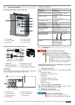
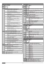
Statusindicatie deurbeweging

Indicati
e

Toestand

Bovenste eindpositie OPEN bereikt

Deureindpositie is niet bereikt

Onderste eindpositie DICHT bereikt

Weergave loopfrequentie deur openen

Weergave loopfrequentie deur sluiten

of

Knipperen van de binnenste segmenten: Timer voor
automatisch sluiten is actief

8

Foutdiagnose

Fout

Toestand

Diagnose

E02

Deur opent of sluit
niet. Veiligheidsin-
gang J4.3/4 geacti-
veerd

Toestand randapparatuur bij
J4.3/4 controleren.

E03

Deur opent of sluit
niet. Loopdeur geo-
pend

Loopdeur sluiten.

E04

De deur opent lang-
zaam

Anti-Crash-sensor geactiveerd.
Beslag/geleiding controleren.

E05

Deur opent of sluit
niet. Veiligheidsscha-
kelaar is geactiveerd

Aansluitleiding 8k2-profiel be-
schadigd, slapkabelschakelaar
controleren.

E06

Deur beweegt niet in
tegengestelde rich-
ting / sluit niet

Sluitkant is geactiveerd. Menu-
punt 35 controleren.

E07

Deur beweegt niet in
tegengestelde rich-
ting / sluit niet

Fotocel is geactiveerd. Menu-
punt 36 controleren.

E08

Deur opent of sluit
niet. DES-veiligheids-
circuit aandrijving ge-
opend

Noodhandbediening geactiveerd.
Motor, thermische schakelaar is
geactiveerd, motoroverbelasting
of blokkering.

E09

Deur opent en sluit
niet

Geen deureindpositie ingeleerd.
Deureindposities inleren onder
menupunt 30 + 31.

E10

Menupunt 36 op
waarde 3 of 4 inge-
steld

Deur volledig openen en sluiten,
zodat de positie van de fotocel
kan worden bepaald.

E11

Deur opent of sluit
niet. Slapkabelscha-
kelaar is geactiveerd

Kabels controleren.

E91

Deur opent of sluit
niet. Permanent-
STOP-commando ge-
detecteerd

STOP-knop bij J1 controleren.
Folieknop STOP ingedrukt.

F01

Geen beweging van
de deur

Feedback-remrelais ontbreekt.

F2
F3
F4

Geen reactie

Fout ontstaan bij zelftest. Bestu-
ring vervangen.

F5

Reset is uitgevoerd

Netomgeving onderzoeken op
elektrische storingsbronnen, af-
stand motorkabel en / of signaal-
leidingen t.o.v. netkabels vergro-
ten, startknop op besturing in-
drukken voor normaal bedrijf.

F10

Deur stopt kort na
startcommando

Storing in de besturingselektroni-
ca. Besturing vervangen.

F19

Deur beweegt alleen
bij dodeman DICHT

Test sluitkant mislukt. Sluitkant-
beveiliging controleren.

F20

Deur beweegt alleen
bij dodeman DICHT

Test fotocel mislukt. Fotocel con-
troleren.

F21

Kortstondige bedrijfs-
onderbreking

Tijdsoverschrijding deurbeweging
gedetecteerd (90 sec.). Deur op
zwaar lopen of blokkade controle-
ren. Eindposities controleren.

F23

Geen reactie

Elektronische deurvergrendeling
EDL100 reageert niet. Bekabeling
controleren. Grendelpen klemt,
grendelpen op zwaar lopen con-
troleren. De deurvergrendeling
niet met olie of vet smeren.

Summary of Contents for T100 R

Page 1: ...ating instructions door control Notice de montage et d utilisation Commande de porte Manual de instrucciones y de montaje Control de port n Montage en gebruikshandleiding deurbesturing Instrukcja mont...

Page 2: ...ns techniques r serv es Variations possibles La composition de la fourniture d pend de la configuration du produit ES Derechos de autor y exenci n de responsabilidad 2020 TORMATIC La reproducci n divu...

Page 3: ...uf wichtige Informationen z B auf Sachsch den aber nicht auf Gef hrdungen hin Infosymbole Info Hinweise mit diesem Symbol helfen Ihnen Ihre T tig keiten schnell und sicher auszuf hren Verweis auf Text...

Page 4: ...diener Der Bediener muss die Anleitung insbesondere das Kapitel Si cherheit gelesen und verstanden haben und sich ber die Gefah ren im Umgang mit dem Produkt bzw der angesteuerten Toran lage im Klaren...

Page 5: ...orleistung max 3 0 kW Sicherheit gem EN 13849 1 Eingang STOPP A Kat 2 PL C Eingang STOPP B Kat 2 PL C Eingang STOPP C Kat 2 PL C Schutzart IP 54 CEE Stecker IP44 Betriebstemperatur 20 C 50 C Herstelle...

Page 6: ...AC erfolgt am An schluss X4 Ausschnitt b Federbruchsicherung Abrollsicherung Bei Ausl sung einer Federbruchsicherung ist die Steuerung durch Federbruch oder Abrollsicherungsschalter gegen Wieder anla...

Page 7: ...e entsprechend der folgenden Va rianten an Abb a 2 Drahtlichtschranke LS2 Abb b 4 Drahtlichtschranke LS5 mit Testung Abb c Reflexionslichtschranke W hlen Sie anschlie end die entsprechende Lichtschran...

Page 8: ...n Sie die Auswahl mit der Taste Im LED Dis play blinkt der aktuell eingestellte Wert f r den jeweiligen Men punkt 6 Stellen Sie den gew nschten Wert mit den Tasten ein Je nach Men punkt k nnen Werte z...

Page 9: ...r stehen Ihnen Werte von 0 bis 99 zur Ver f gung Werte von 50 Werkseinstellung bis 0 entsprechen 0 mm bis ca 80 mm Werte ab 50 bis 99 entsprechen 0 mm bis ca 80 mm Auswahl Schlie kante J3 Auswahl Lich...

Page 10: ...n sowie die gew nschte Betriebsart f r die Starttaste ausw hlen Men 7 Antriebseinstellungen Startimpuls Men punkte 70 72 Um einem ruhigen Torlauf zu erreichen stellen Sie unter Men punkt 70 und 72 ein...

Page 11: ...llreversieren Werkseinstellung 1 Teilreversieren 44 Offenhaltezeit in Sekunden Men 4 weitere Toreinstellungen Men punkt Eingabe Auswahl 0 0 s Werkseinstellung 1 30 1 s 30 s in 1 s Schritten 31 60 35 s...

Page 12: ...abe Auswahl 70 Softstart mit reduziertem Drehmoment 0 aus 1 13 Zeit 60 ms 300 ms in 20 ms Stufen 71 0 40 Auslaufweg vor oberer Endlage in cm 10 cm Werkseinstellung 72 0 20 reduziertes Drehmoment 16 We...

Page 13: ...Diese Betriebsart verlangt die Installation einer Schlie kantensi cherung Men punkt 35 Ein Ausl sen der Schlie kantensiche rung bewirkt w hrend der Schlie fahrt ein Stoppen und eine Richtungsumkehr W...

Page 14: ...sgel st Be hang F hrung pr fen E05 Tor f hrt weder auf noch zu Sicherheits schalter hat ausgel st Anschlussleitung 8k2 Leiste be sch digt Schlaffseilschalter ber pr fen E06 Tor reversiert schlie t nic...

Page 15: ...f hrt weder auf noch zu Testung Ein gang J4 1 2 fehlge schlagen Steuerung aus und einschalten Ggf Steuerung tauschen F74 Tor f hrt weder auf noch zu Testung Ein gang J4 3 4 fehlge schlagen Steuerung...

Page 16: ...umusterpr fzertifikat 44 780 13108301 Produktmodell Produkt T100 R Produkttyp Torsteuerung Baujahr ab 01 2021 geeignet f r Torantriebe NovoShaft 9 15 9 20 9 24 14 15 SI8 120 SI20 90 SI35 60 SI4 5 90 E...

Page 17: ...l gelgewicht Torabmessungen Einbau und Inbetriebnahme Firma Monteur Firma Monteur Inbetriebnahme am Unterschrift Sonstige Angaben Nachtr gliche nderungen Pr fungs und Wartungsnachweise der Toranlage D...

Page 18: ...2 4 Rundlauf T Welle Zustand 3 0 Antrieb Steuerung 3 1 Antrieb Konsole Zustand Befestigung 3 2 Elektrische Leitungen Anschl sse Zustand 3 3 Notentriegelung Zustand Funktion 3 3 1 Schnelle Kette Zusta...

Page 19: ...asks quickly and safely Refers to text and image a Refers to a graphic of the corresponding connection variant in the Connection diagrams chapter 2 Safety Observe the following safety information WARN...

Page 20: ...ust be aware of the hazards associated with handling the product and the controlled door sys tem The operator must have been instructed with regard to handling the controlled door system Dangers which...

Page 21: ...rnal power supply max 700 mA Max motor power Max 3 0 kW Safety according to EN 13849 1 Input STOP A Cat 2 PL C Input STOP B Cat 2 PL C Input STOP C Cat 2 PL C Protection type IP 54 CEE plug IP44 Opera...

Page 22: ...cted to connection X4 Detail b Spring fracture safety device roll down locking mech anism If a spring fracture safety device is tripped the control must be protected against restart by spring fracture...

Page 23: ...ectric sensor Connect the photoelectric sensor as specified for the following variants Fig a 2 wire photoelectric sensor LS2 Fig b 4 wire photoelectric sensor LS5 with testing Fig c Reflection light b...

Page 24: ...the button The currently set value for the respective menu item blinks on the LED dis play 6 Set the desired value using the buttons Depending on the menu item values between 0 and 99 can be entered 7...

Page 25: ...tem 34 Fine correc tion lower end position 4 Values 0 to 99 are provided to you for carrying out a fine correction Values of 50 default setting to 0 correspond to 0 mm to approx 80 mm Values from 50 t...

Page 26: ...d the dot display on the display blinks 5 times Selecting the hand held transmitter operating mode menu item 64 In menu item 64 you can temporarily disable the taught in hand held transmitters and sel...

Page 27: ...fault setting 3 AR automatic closing 41 Response to closing edge safety device 0 Full reversing default setting 1 Partial reversing Menu 4 Further door settings Menu item Entry Selection 44 Hold open...

Page 28: ...peration open stop close 2 Automatic closing AR 3 Open close operation Exit menu Menu 7 drive settings Menu item Entry Selection 70 Soft start with reduced torque 0 Off 1 13 Time 60 ms 300 ms in steps...

Page 29: ...mode requires the installation of a closing edge safety device menu item 35 When the closing edge safety device is activated while the door is closing the door will stop and a direction reversal will...

Page 30: ...i crash sensor triggered Check door door guide E05 Door neither opens nor closes Safety switch has triggered Connection line 8k2 strip dam aged check slack rope switch E06 Door reverses does not close...

Page 31: ...itch control on and off If ne cessary replace control F74 Door neither opens nor closes Testing of input J4 3 4 failed Switch control on and off If ne cessary replace control F75 Door neither opens no...

Page 32: ...ation certificate 44 780 13108301 Product model product T100 R Product type Door control Year of manufacture from 01 2021 Suitable for door drives NovoShaft 9 15 9 20 9 24 14 15 SI8 120 SI20 90 SI35 6...

Page 33: ...ufacture Serial No Wing weight Door dimensions Installation and commissioning Company technician Company technician Commissioning on Signature Other details Subsequent changes Proof of inspection and...

Page 34: ...4 Concentricity of T shaft State 3 0 Drive control 3 1 Drive console State fastening 3 2 Electrical cables connections State 3 3 Emergency release State function 3 3 1 Quick chain State function 3 3 2...

Page 35: ...d crasement pour les membres du corps humain Risque de happement Ce symbole vous signale des situations dangereuses pr sentant un risque de happement Symboles indicatifs AVIS AVIS signale des informat...

Page 36: ...ler le logiciel de commande garantir la capa cit fonctionnelle des composants lectriques et d tecter les risques ventuels lors de la manipulation de syst mes lectriques et lectroniques Les personnes s...

Page 37: ...XX XX XXXXXXXXXX 7 1 2 3 4 5 6 1 Type de commande 5 Puissance moteur maximum 2 Fabricant et adresse 6 Indice de protection 3 Tension d alimentation 7 No de la plaque signal tique 4 Intensit Caract ri...

Page 38: ...term diaire d un dispositif de coupure multipolaire 10 A selon EN 12453 Assurez vous que ce disjoncteur une fois l ins tallation effectu e soit facile d acc s AVIS Contr le du raccordement secteur Ass...

Page 39: ...raccordement de porte avec un capteur Break Away et une tranche de s curit OSE Fig c Raccordez une prise de raccordement de porte avec un capteur Break Away et une tranche de s curit 8k2 En cas d util...

Page 40: ...la mani re suivante 1 Appuyez sur la touche afin d acc der la programma tion de la commande L affichage LED indique le num ro des divers menus principaux ci apr s d sign s comme menus Vous avez jusqu...

Page 41: ...Sortez du sous menu 30 en appuyant une fois sur la touche Le point de l affichage LED clignote 5 fois et confirme ainsi la saisie 4 Passez au menu 31 R glage de la porte position finale basse 5 Pour d...

Page 42: ...Loq 12 Bit Multibit Le premier code appris d termine le type de cryptage Impulsion de d marrage sous menu 60 1 S lectionnez le sous menu 60 Apprentissage touche d marrage de l metteur 2 Actionnez la t...

Page 43: ...maintien en posi tion ouverte r glage usine 1 R duction du temps de maintien en position ouverte en mode AR Sortie menu Menu 4 Autres r glages de la porte Sous menu Saisie S lection 40 S lection mode...

Page 44: ...tranche de s curit sans fil option 6 7 r serv 55 R glage de la porte pour position EFC Sortie menu Menu 6 R glages radio Sous menu Saisie S lection 60 Apprentissage touche d marrage de l metteur 61 Ap...

Page 45: ...fermer Lorsque la porte se ferme elle peut cogner les personnes ou entrer en collision avec elles La porte doit pouvoir tre vue partir de l endroit o on la commande Description des fonctions pour le...

Page 46: ...uption du temps de maintien en position ouverte et le d marrage du temps de pr avis Une fois le temps de pr avis coul la porte se ferme automatiquement Demi ouverture de porte L activation de la touch...

Page 47: ...bas Com mande STOP perma nente d tect e Contr ler la touche STOP sur J1 Touche membrane STOP acti v e F01 Aucun d placement du portail L information de retour du relais de freinage est en d faut F2 F3...

Page 48: ...teurs non valides d tect s J4 3 4 Contr ler les r sistances Contr ler les capteurs F78 Entra nement se bloque en position fi nale FERM E Contr ler la tension des ressorts la m canique de la porte la p...

Page 49: ...2 1 5 4 1 5 5 1 5 6 1 6 2 1 6 3 1 7 Normes harmonis es applicables EN ISO 12100 2010 EN 12978 2003 A1 2009 EN 13241 2003 A2 2016 EN ISO 13849 1 2015 PL c cat 2 EN 60335 1 2012 AC 2014 EN 61000 6 3 20...

Page 50: ...de fabrication N de s rie Poids du vantail Dimensions de la porte Montage et mise en service Entreprise monteur Entreprise monteur Mise en service le Signature Autres indications Modifications ult ri...

Page 51: ...en T tat 3 0 Motorisation commande 3 1 Motorisation console tat fixation 3 2 C bles lectriques raccordements tat 3 3 D verrouillage d urgence tat fonctionnement 3 3 1 Cha ne rapide tat fonctionnement...

Page 52: ...no peligros S mbolos de informaci n Info Las indicaciones con este s mbolo le ayudan a realizar su actividad de forma m s r pida y segura Indicaci n sobre texto e imagen a Indica un gr fico de las op...

Page 53: ...comprendido el manual en espe cial el cap tulo Seguridad y conocer con claridad los peligros de rivados del uso del producto o del sistema de port n controlado El operario debe haber sido instruido so...

Page 54: ...0 kW Seguridad conforme a norma EN 13849 1 Entrada PARADA A Cat 2 PL C Entrada PARADA B Cat 2 PL C Entrada PARADA C Cat 2 PL C Tipo de protecci n IP 54 Clavija CEE IP44 Temperatura de servicio 20 C 50...

Page 55: ...conecta un transmisor de se ales externo a la conexi n J1 del control tiene a su disposici n las siguientes opciones Il a b Conexi n a J1 para transmisores de se ales externos con ABRIR PARAR y CERRAR...

Page 56: ...tada en el marco en el siguiente ciclo hacia la posici n CIERRE el control realiza un ciclo de programaci n para detectar la posici n AVISO No interrumpa el ciclo de programaci n No se debe interrumpi...

Page 57: ...a seleccionar el punto de men Tiene a su disposici n hasta 10 puntos de men s 0 9 La segunda cifra de la pantalla de led muestra la se lecci n actual como un valor 0 9 5 Confirme la selecci n con la t...

Page 58: ...tecla y mant ngala presionada hasta que el port n haya alcanzado la posici n que desee 3 Confirme su selecci n para concluir la configuraci n Configuraci n precisa del port n en la posici n final supe...

Page 59: ...minaci n punto de men 62 Seleccione el punto de men 62 y pulse la tecla del mando a dis tancia para la funci n de iluminaci n Una vez programado el ci frado el indicador de puntos parpadea 5 veces en...

Page 60: ...de f brica 25 0 0 50 mm m s abajo 25 99 0 100 mm m s alto 38 Reacci n de barrera fotoel ctrica 0 Sin reducci n del tiempo de apertura configu raci n de f brica 1 Reducci n del tiempo de apertura en f...

Page 61: ...Reservado 55 Configuraci n del port n para la posici n SC TEH Salir del men Men 6 Inal mbrica Punto de men Valor introdu cido Selecci n 60 Programar la tecla de arranque del mando a distancia 61 Prog...

Page 62: ...tiene de inmediato Acceso de personas no autorizadas solo con interruptor de llave y en modo de hombre muerto Impulso ABRIR Hombre muerto CERRAR Pulsando brevemente la tecla o mediante el transmisor d...

Page 63: ...le o se dispare por equivocaci n alg n dispositivo de seguridad Al aparecer en pantalla E06 o E07 el funcionamiento de emer gencia se activa manteniendo pulsada 5 segundos la tecla ABRIR o CERRAR y se...

Page 64: ...ro del canto de cierre Error Estado Diagn stico F20 El port n solo se des plaza al CIERRE en el modo de hombre muerto Error en la comprobaci n de la barrera fotoel ctrica Revisar la barrera fotoel ctr...

Page 65: ...o mec nico del port n y la posici n final CIERRE L El accedo al men ha sido bloqueado por el distribuidor autoriza do Contactar con el distribuidor El men solo se puede desbloquear mediante la herrami...

Page 66: ...aci n a partir de 01 2021 Apto para sistemas de port n NovoShaft 9 15 9 20 9 24 14 15 SI8 120 SI20 90 SI35 60 SI4 5 90 Directivas UE aplicables 2014 30 UE Directiva 2011 65 UE RoHS por sus siglas en i...

Page 67: ...N de serie Peso de la hoja Dimensiones del por t n Montaje y puesta en funcionamiento Empresa instalador Empresa instalador Puesta en funciona miento el Firma Otras indicaciones Modificaciones posteri...

Page 68: ...tra ca das Estado 2 4 Concentricidad del rbol T Estado 3 0 Accionamiento control 3 1 Accionamiento consola Estado fijaci n 3 2 Cables el ctricos Conexiones Estado 3 3 Desbloqueo de emergencia Estado f...

Page 69: ...fo Aanwijzingen met dit symbool helpen u bij het snel en veilig uitvoeren van uw taken Verwijzing naar tekst en afbeelding a Verwijst naar een afbeelding van de betreffende aan sluitvariant in hoofdst...

Page 70: ...r de bediening van het product Bediener De bediener moet de handleiding vooral het hoofdstuk veiligheid hebben gelezen en begrepen en op de hoogte zijn van de geva ren bij de omgang met het product re...

Page 71: ...B Cat 2 PL C Ingang STOP C Cat 2 PL C Beschermingsgraad IP 54 CEE stekker IP44 Bedrijfstemperatuur 20 C 50 C Fabrikant Novoferm tormatic GmbH Eisenh ttenweg 6 D 44145 Dortmund www tormatic de 4 Instal...

Page 72: ...andogever met OPEN STOP en DICHT Afb c Aansluiting op J1 voor externe commandogever met een schakelvolgorde OPEN STOP DICHT J1 3 deuropening J1 4 volledige deuropening Menupunt 51 instellen op de waar...

Page 73: ...positie te registreren 13 Anti Crash sensor Via een aangesloten Anti Crash sensor detecteert ingang J6 als het gordijn uit de geleiding is gesprongen en zorgt dat hier auto matisch weer in wordt inge...

Page 74: ...p Op het LED display knippert de ingestelde waarde voor het betreffende menu punt 6 De gewenste waarde instellen met de knoppen Af hankelijk van het menupunt kunnen waarden tussen 0 en 99 worden ingev...

Page 75: ...ca 80 mm Waarden van 50 tot en met 99 komen overeen met 0 mm tot en met ca 80 mm Keuze sluitkant J3 keuze fotocel J4 menupunt 35 en 36 1 Kies menu 3 Basisinstellingen bij de besturing en ga naar menup...

Page 76: ...stige deurloop bij menupunt 70 en 72 een softstart in stellen en bij menupunt 71 evenals een softstop voor het berei ken van de bovenste eindpositie Draadloze sluitkant RadioBand Het RadioBand systeem...

Page 77: ...bewegingsrichting fa brieksinstelling 1 Gedeeltelijke omkering van bewegingsrichting Menu 4 uitgebreide deurinstellingen Menu punt Invoer Keuze 44 Openhoudtijd in seconden 0 0 s fabrieksinstelling 1 3...

Page 78: ...bedrijf Menu be indigen Menu 7 Aandrijvingsinstellingen Menu punt Invoer Keuze 70 Softstart met gereduceerd koppel 0 Uit 1 13 Tijd 60 ms 300 ms in stappen van 20 ms 71 0 40 Uitloopweg voor bovenste ei...

Page 79: ...bereikt Deze bedrijfsmodus vereist het installeren van een sluitkantbevei liging menupunt 35 Activering van de sluitkantbeveiliging zorgt tijdens de sluitbeweging voor het stoppen en een richtingsomk...

Page 80: ...Crash sensor geactiveerd Beslag geleiding controleren E05 Deur opent of sluit niet Veiligheidsscha kelaar is geactiveerd Aansluitleiding 8k2 profiel be schadigd slapkabelschakelaar controleren E06 De...

Page 81: ...ng uit en inschakelen In dien nodig besturing vervangen F74 Deur opent of sluit niet Test ingang J4 3 4 mislukt Besturing uit en inschakelen In dien nodig besturing vervangen F75 Deur opent of sluit n...

Page 82: ...Productmodel product T100 R Producttype Deurbesturing Bouwjaar vanaf 01 2021 Geschikt voor deuraandrijvingen NovoShaft 9 15 9 20 9 24 14 15 SI8 120 SI20 90 SI35 60 SI4 5 90 Van toepassing zijnde EU Ri...

Page 83: ...ar Serienr Bladgewicht Deurafmetingen Inbouw en inbedrijfstelling Firma monteur Firma monteur Inbedrijfstelling op Handtekening Overige gegevens Wijzigingen naderhand Controle en onderhoudslogboek van...

Page 84: ...eiliging Toestand 2 4 Rondloop T as Toestand 3 0 Aandrijving besturing 3 1 Aandrijving console Toestand bevestiging 3 2 Elektrische leidingen aansluitingen Toestand 3 3 Noodontgrendeling Toestand func...

Page 85: ...iesienie do tekstu i obrazu a Stanowi odniesienie do schematu dla odpowiedniego wariantu przy czenia zamieszczonego w rozdziale Schematy po cze 2 Bezpiecze stwo Uwzgl dnij nast puj ce wskaz wki dotycz...

Page 86: ...u Bezpiecze stwo oraz musi mie wia domo zagro e zwi zanych z obs ug produktu lub sterowane go systemu bramy Operator musi by przeszkolony w zakresie obs ugi sterowanego systemu bramy Zagro enia kt re...

Page 87: ...e 24 V DC Zasilanie zewn trzne maks 700 mA Maks moc silnika maks 3 0 kW Bezpiecze stwo zgodnie z EN 13849 1 Wej cie STOPP A Kat 2 PL C Wej cie STOPP B Kat 2 PL C Wej cie STOPP C Kat 2 PL C Stopie ochr...

Page 88: ...zenie przed ponownym uruchomieniem Zadanie to jest realizowane za po rednictwem czujnika zabezpieczenia przed zerwaniem spr yny i samoczyn nego zamkni cia si bramy Zastosuj czujniki w wersji normalnie...

Page 89: ...czenia bramek wietlnych Ilustr a 2 przewodowa bramka wietlna LS2 Ilustr b 4 przewodowa bramka wietlna LS5 z funkcj testu Ilustr c Odblaskowa bramka wietlna Nast pnie wybierz odpowiedni fotokom rk w pu...

Page 90: ...y punkt menu cznie dost pnych jest do 10 punkt w menu 0 9 Druga cyfra wska nika LED wskazuje aktualny wyb r jako warto 0 9 5 Potwierd wyb r przyciskiem Aktualnie ustawiona warto dla danego punktu menu...

Page 91: ...a g rnego po o enia kra cowego punkt menu 33 i dolnego po o enia kra cowego punkt menu 34 bramy 1 Wybierz w sterowaniu menu 3 Ustawienia podstawowe i przejd do punktu 33 menu Dok adna regulacja g rneg...

Page 92: ...ik punktowy na wy wietlaczu b y nie 5 razy Usuwanie kod w radiowych punkt 63 menu W celu usuni cia zaprogramowanych kod w wykonaj nast puj ce czynno ci 1 Wybierz punkt 63 menu 2 Naci nij i przytrzymaj...

Page 93: ...akcja bramki wietlnej 0 Bez skr cenia czasu otwarcia ustawienie fa bryczne 1 Skr cenie czasu otwarcia w trybie AR Wyjd z menu Menu 4 inne ustawienia bramy Punkt menu Wpro wadzo na warto Wyb r 40 Wyb r...

Page 94: ...0 wy czona ustawienie fabryczne 1 2 3 4 Modu DC 5 Modu RadioSafe bezprzewodowa kraw d zamykaj ca opcja 6 7 zarezerwowany 55 Ustawienie bramy w pozycji RWA Wyjd z menu Menu 6 Radio Punkt menu Wpro wadz...

Page 95: ...y Je li przy cisk zostanie zwolniony podczas zamykania brama zatrzyma si natychmiastowo Dost p do os b nie posiadaj cych odpowiedniego prze szkolenia tylko z zastosowaniem prze cznika kluczykowego i t...

Page 96: ...y w przypadku uszko dzenia lub zadzia ania urz dzenia zabezpieczaj cego Tryb awaryjny jest uruchamiany przy wskazaniu E06 lub E07 po przez ci g e naci ni cie przycisku Otw rz lub Zamknij przez 5 sekun...

Page 97: ...aj cej nie powi d si Sprawd zabezpie czenie kraw dzi zamykaj cej Usterka Stan Diagnoza F20 Zamkni cie bramy mo liwe jest tylko w trybie p automa tycznym Test bramki wietlnej zako czy si niepowodzeniem...

Page 98: ...ealera Skontaktuj si z dealerem Odblo kowanie menu jest mo liwe tylko przy u yciu narz dzia serwisowe go Lo Sterowanie zosta o wy czone Skontaktuj si z dealerem Odblo kowanie menu jest mo liwe tylko p...

Page 99: ...i od 01 2021 Przeznaczony do nap d w bram NovoShaft 9 15 9 20 9 24 14 15 SI8 120 SI20 90 SI35 60 SI4 5 90 Dyrektywy WE dotycz ce urz dzenia 2014 30 UE 2011 65 UE Dyrektywa RoHS w tym za cznik II zgodn...

Page 100: ...nstrukcji Rok produkcji Numer seryjny Masa skrzyd a Wymiary bramy Instalacja i uruchomienie Firma monta ysta Firma monta ysta Uruchomienie dnia Podpis Inne informacje P niejsze zmiany Dokumentacja kon...

Page 101: ...eczenie przed opadni ciem Stan 2 4 Bicie wa ka T Stan 3 0 Nap d sterowanie 3 1 Nap d konsola Stan mocowanie 3 2 Kable elektryczne po czenia Stan 3 3 Odblokowanie awaryjne Stan sprawno 3 3 1 Szybki a c...

Page 102: ...erung Assembly of the control Montage de la commande Montage van de besturing Montaje del control Monta sterowania 182 mm 242 mm 1400 mm 4 Anschluss Benennung Terminal designation D no mination des ra...

Page 103: ...ele menty sterowania a 1 1 1 2 1 3 J1 1 4 NC NO NO b 1 1 1 2 1 3 J1 1 4 c 1 2 1 3 J1 1 4 1 1 d J1 1 1 1 2 1 3 1 4 8b 1 8b 2 8b 3 8b 4 X8a 8a 1 8a 2 8a 3 X8b 5 1 2 3 4 6 8 Timereing nge Timer inputs En...

Page 104: ...port n Puszka przy czeniowa bramy a 2k 2k 8k2 J4 J3 4 1 4 2 3 1 3 2 3 3 WH GN BN YE GY b 1 2 3 4 5 6 J3 gn br 1 6 J4 3 1 3 2 3 3 4 1 4 2 4 3 4 4 br gn wh wh 2k 2k c 1 2 3 4 5 6 J3 gn br 1 6 J4 3 1 3...

Page 105: ...ELS 300 NO BN BK BU 14 STOPP Kreis STOP circuit Circuit d ARR T STOP circuit Circuito de PARADA Obw d zatrzymania a 4 1 4 2 4 3 J4 4 4 4 k b 4 1 4 2 4 3 J4 4 4 4 k 15 Schl sselschalter Zugschalter Ke...

Page 106: ...X5 X6 1 1 5 2 5 1 5 3 1 1 6 2 6 1 6 3 J4 4 1 4 2 4 3 4 4 DOOR 2 X5 X6 1 1 5 2 5 1 5 3 1 1 6 2 6 1 6 3 J4 4 1 4 2 4 3 4 4 d DOOR 3 X5 X6 1 1 5 2 5 1 5 3 1 1 6 2 6 1 6 3 J4 4 1 4 2 4 3 4 4 DOOR 2 X5 X6...

Page 107: ......

Page 108: ...Novoferm tormatic GmbH Eisenh ttenweg 6 44145 Dortmund...

Reviews: