background image

12

ATTENTION:

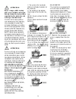
Never charge a GEL battery 

with a non suitable recharger. 

Strictly follow the instructions 

supplied by the batteries and 

recharger manufacturer.

In order not to cause perma-

nent damages to the batteries, 

it is necessary to avoid their 

complete discharge, providing 

for the recharging within a few 

minutes after the batteries dis-

charge signal starts blinking.

NOTE: Never leave batteries 

completely discharged even if 

the machine is not used. In case 

of traditional batteries, please 

check the electrolyte level every 

20 recharging cycles and even-

tually top them up with distilled 

water.

ATTENTION:

1. The version (for example 

A003) of software installed on 

the machine.

2. The setting of the battery 

check card is for the 24V ver-

sion:

GE 24: check card set for GEL 

batteries

Pb 24: check card set for lead 

batteries

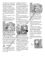
For the recharge of the batteries 

it is necessary to follow strictly 

all the indications given by the 

manufacturer/distributor. All the 

installation and maintenance 

operations must be carried out 

by qualified staff. 

Danger of 

gas exhalations and emis-

sion of corrosive liquids. Fire 

danger: do not approach with 

free flames.

BATTERIES DISPOSAL

It is compulsory to hand over 

exhausted batteries, classified 

as dangerous waste, to an au-

thorized institution according to 

the current laws.

BATTERIES CHARGE LEVEL 

INDICATOR

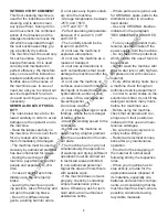
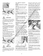
TURNING THE KEY (9) 

CLOCKWISE, ON THE DIS-

PLAY (1) APPEAR IN SE-

QUENCE THE FOLLOWING 

INFORMATION:

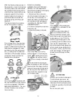
3. The batteries charge level 

indicator (1) is digital. The bat-

tery charge level starts at 90, 

which indicates the 90% of the 

total charge and decreases by 

10 to 10. When the charge level 

reaches 20%, the display starts 

blinking, so you are about at the 

end of working time.

After a few seconds from the 

blinking of the four lines, the 

brushes motor stops automati-

cally. With the remaining charge 

it is anyhow possible to finish 

the drying operation before pro-

ceeding to the recharge area.

ATTENTION:

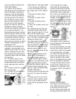
HOUR METER

The machine is equipped with 

an hour meter located on the 

same display of the battery 

charge level indicator (1). Keep-

ing the button (8) pressed for 

more than 3 seconds, the first 

data indicates the working hours 

and after a few seconds the 

working minutes are shown.

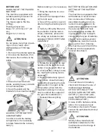
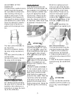
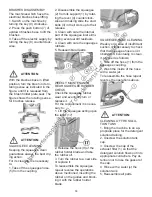
SQUEEGEE ASSEMBLY

1. Maintain the squeegee sup-

port (1) slightly lifted from the 

floor.

2. Insert the two stud bolts (3) 

placed on the upper part of the 

squeegee (2) inside the slots on 

the support.

3. Block the squeegee by rotat-

ing the lever (4) clockwise.

4. Insert the squeegee hose 

(5) into its coupling, respecting 

its position as indicated in the 

figure.

https://harrissupplyind.com - To Order Parts Call 608-268-8080

Summary of Contents for 99732

Page 1: ...51 0719 WWW TORNADOVAC COM Operations Maintenance Manual For Commercial Use Only Form No L9732AB 03 17 Tornado Industries LLC All rights reserved BD 32 26 AUTOMATIC SCRUBBER MODEL NO 99732 h t t p s h a r r i s s u p p l y i n d c o m T o O r d e r P a r t s C a l l 6 0 8 2 6 8 8 0 8 0 ...

Page 2: ...e 1 Except all Windshears Blowers Storm TV2SS Side and Downdraft Insulation Blowers CV 30 CV 38 CK14 1 PRO CK 14 2 PRO SWM 31 9 CK LW13 1 CK LW 13 1 ROAM CV 38 48 Dual PV6 PV10 PV6 ROAM Wall Mount Vacuum and all chargers are warranted for 1 one year for both parts and labor 2 All non wear item parts purchased after warranty expiration are warranted for 90 days 3 Warranty starts from the date of sa...

Page 3: ...3 NOTES h t t p s h a r r i s s u p p l y i n d c o m T o O r d e r P a r t s C a l l 6 0 8 2 6 8 8 0 8 0 ...

Page 4: ...ment 16 Working brake 16 Emergency brake 16 Adjustment of the brushes pressure 16 Brushes motor overload protection device 16 Overflow device 17 STOP OF THE MACHINE AFTER CLEANING OPERATION 17 DAILY MAINTENANCE 17 Recovery tank cleaning 17 Suction filter cleaning 17 Brushes cleaning 17 Brushes disassembly 18 Squeegee cleaning 18 WEEKLY MAINTENANCE 18 Rear squeegee rubber check 18 Squeegee hose cle...

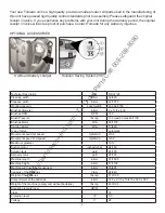
Page 5: ...es V Ah5 24 240 Weight of the batteries lbs kg 419 190 Compartment of the batteries in mm 16 5 x 20 5 x 15 415 x 520 x 385 Weight of the machine empty and without batteries lbs kg 430 195 Acoustic pressure level dB A Class III Protection level IP X3 Voltage V 24 OPTIONAL ACCESSORIES On Board battery charger Solution Saving System 3S Your new Tornado unit is a high quality precision made product Al...

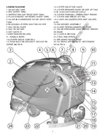
Page 6: ...WITCH WITH KEY 10 INSTRUMENT BOARD 11 HANDLE BARS 12 LEVERS DRIVE CONTROL 13 SECURITY DEVICE REVERSE MOTION 14 LEVER SOLUTION VALVE 15 LEVER BRUSHES BASE GROUP LIFTING only version with hydraulic pump 16 LEVER PARKING EMERGENCY BRAKE 17 LEVER SQUEEGEE LIFTING LEGEND INSTRUMENT BOARD AND CONTROLS h t t p s h a r r i s s u p p l y i n d c o m T o O r d e r P a r t s C a l l 6 0 8 2 6 8 8 0 8 0 ...

Page 7: ...CTION WHEELS 24 BRUSHES BASE GROUP 25 SCREW CAP FOR INLET DETERGENT SOLUTION LEGEND MACHINE 1 SOLUTION TANK 2 RECOVERY TANK 3 INSPECTION CAP RECOVERY TANK 4 PLUG EXHAUST HOSE RECOVERY TANK 5 COUPLING SQUEEGEE HOSE RECOVERY TANK 6 BLOCKING LEVERS SUCTION COVER 7 SUCTION COVER 8 SUCTION HOSE 9 KEY SWITCH 10 INSTRUMENT BOARD 11 HANDLE BARS 12 LEVERS DRIVE CONTROL 13 PUSH BUTTON SECURITY DEVICE RE VER...

Page 8: ...considering that the machine itself has been where possible constructed using recyclable materials Do not place any liquid contain ers onto the machine Storage temperature between 25 C and 55 C 13 F and 131 F Perfect operating temperature between 0 C and 40 C 32 F and 104 F The humidity should be be tween 30 and 95 Do not use the machine in explosive atmosphere Do not use the machine as a means of...

Page 9: ...noting the hour meter Indication of the maxi mum temperature of the solution detergent It is placed near the charg ing hole of the solution tank Symbol denoting the brake Indicates the signal lamp of the brake on Symbol denoting the brake Indicates the lever of the emergency and parking brake Symbol denoting the crossed bin Indicates that at the end of its activity the machine has to be disposed c...

Page 10: ... maximum opening can be obtained 6 Having finished any type of intervention close the battery compartment pushing the tank downwards if it is open at the first position while from the maximum opening it is neces sary to unblock the support of the gas shock absorber 1 7 Reassemble everything BATTERY INSTALLATION AND SETTING OF THE BATTERY TYPE The machine is equipped either with batteries in serial...

Page 11: ...tery recharger is con nected directly to the battery poles During the recharging opera tions a device is activated which does not permit the machine s functioning The mains cable of the bat tery recharger has a maximum length of two metres and must be connected to a single phase socket type CEE 7 7 BATTERIES RECHARGING For batteries recharge it is necessary to reach the battery compartment as indi...

Page 12: ...fied as dangerous waste to an au thorized institution according to the current laws BATTERIES CHARGE LEVEL INDICATOR TURNING THE KEY 9 CLOCKWISE ON THE DIS PLAY 1 APPEAR IN SE QUENCE THE FOLLOWING INFORMATION 3 The batteries charge level indicator 1 is digital The bat tery charge level starts at 90 which indicates the 90 of the total charge and decreases by 10 to 10 When the charge level reaches 2...

Page 13: ...ction results to be high need little pressure while smooth floors ceramics need higher pressure If the cleaning operations are made always on the same type of floor the adjustment can change only in function of the rubber wear SPLASH GUARD ASSEMBLY The two splash guards have to be assembled onto the brushes base group Insert the metal strips inside the suitable slots present on the rubber Place th...

Page 14: ...BATTERY COMPARTMENT 2 Connect instead the machine connector 2 3 Close the battery compart ment RECOVERY TANK Check that the cover of the suction filter 1 is correctly se cured after rotating the levers 2 and that the suction motor hose 3 is correctly connected to it Verify also that the squeegee hose couplings 4 are correctly inserted into the seats that the exhaust hose plug 5 placed in the front...

Page 15: ... auto matically acting upon the levers drive control 12 On the instru ment board the indicator of the solenoid valve switch 5 will turn on Releasing these levers will stop the flow Models equipped with the 3S optional it is necessary to press the suitable switch to activate the detergent solution supply by choosing between the traditional adjustment system through the solution valve or the system ...

Page 16: ...e levers drive control 12 ADJUSTMENT OF THE BRUSHES PRESSURE Through the register 1 it is possible to adjust the brushes pressure on the cleaned sur face By turning the knob clockwise the pressure increases rotating it counterclockwise the pres sure decreases This device allows a more ef ficient cleaning action on very difficult and dirty surfaces ATTENTION The control of the adjustment value of t...

Page 17: ...4 Lift the squeegee acting upon the lever 17 5 Bring the machine to an ap propriate place for tanks drain ing 6 Turn the key 9 counterclock wise 7 Insert the parking brake 16 DAILY MAINTENANCE RECOVERY TANK CLEANING 1 Hold the exhaust hose placed in the front part of the machine 2 Take off the plug of the ex haust hose acting upon its lever and empty the recovery tank into appropriate containers 3...

Page 18: ...UBBER CHECK Check the squeegee rubber wear and eventually turn or replace it For the replacement it is neces sary to 1 Lift the squeegee acting upon the lever 17 2 Release the hook 9 of the rubber holder blade and take the rubber off 3 Turn the rubber to a new side or replace it To reassemble the squeegee repeat reverse the operations above mentioned inserting the rubber on the guides and block in...

Page 19: ...structions as under paragraph SPLASH GUARD ASSEMBLY With brushes assembled the splash guard must slightly touch the floor Empty the solution tank remove the fitting of the water outlet by taking off the two screws which fix it to the tank Clean the in side part of the fitting of dirt and debris Pour some water into the tank to clean it Reassemble the fitting onto the solution tank CHECK OF THE BRA...

Page 20: ...ome down clean the filter inside the solution tank Empty the solution tank remove the fitting of the water outlet by taking off the two screws which fix it to the tank Clean the in side part of the fitting of dirt and debris Pour some water into the tank and clean it Reassem ble the fitting onto the solution tank If the problem persists please contact the authorized technical assistance THE DETERG...

Page 21: ...t has been used Eventually add small quantities of anti foam liquid into the recovery tank Please be aware that a bigger quantity of foam is produced when the floor is not very dirty In this case please dilute deter gent solution INTERVENTION DAILY 20 HOURS 200 HOURS 1000 HOURS RECOVERY TANK CLEANING SUCTION FILTER CLEANING SOLUTION TANK FILTER CLEANING BRUSHES CLEANING BRUSHES DISASSEMBLY AND CLE...

Page 22: ...istics over time TYNEX Nylon bristles with grains of abrasive material Use with caution in order not to mark the floor or ruin the polish BRISTLE THICKNESS Thicker bristles are more rigid and must be used on smooth floor or floor with small joints On irregular floors with deep joints or relieves it is recommended to use softer bristles which penetrate more easily and deeper Please be aware that wh...

Page 23: ...re feet meters Total Hard Floor Area Total Carpeted Area Square feet square meters o Contacted by local dealer o Previous experience with Tornado products o Reputation Recommendation o Advertising o Direct mail o Internet o Other o 0 10 000 0 930 o 10 50 000 930 4 650 o 50 250 000 4 650 23 250 o Over 250 000 over 23 260 o 0 10 000 0 930 o 10 50 000 930 4 650 o 50 250 000 4 650 23 250 o Over 250 00...

Reviews: