background image

13

BRUSHES ASSEMBLY

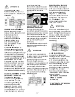
To assemble the brushes it is 
necessary that the brushes 
base is in the lifted position. 
If it is not lifted, proceed as 
follows:
Without the operator seated, 
turning the key switch 
clockwise, the display comes 
on and after 3 seconds all 
working groups come off 
automatically and are lifted 
from the floor.
Switch off the machine turning 
the key counterclockwise. 
spring until they get blocked.  
The figure shows the rotating 
direction for brushes coupling.

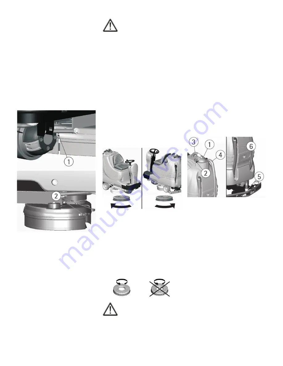
For a longer life of the brushes 
we suggest to invert daily their 
position. Whenever brushes 
become de¬formed we 
suggest to reassemble them in 
the same position, in order to  
avoid the different inclination 
of the bristles to cause 
excessive motor overload or 
troublesome vibrations.

FLOOR CLEANING

RECOVERY TANK

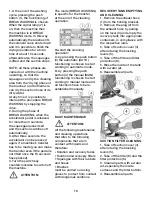
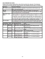
Check that the cover of the 
suction filter (1) is correctly 
secured, after rotating the 
levers (2) and that the suction 
motor hose (3) is correctly 
connected to it.
Verify also that the squeegee 
hose couplings (4/5) are 
correctly inserted into their 
seats and that the exhaust 
hose plug (6) placed in the 
rear part of the machine is well 
closed.

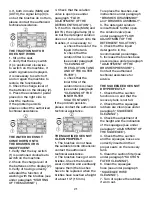
Block the coupling lever (2) in 
the rear part of the brushes 
base group to the ring placed 
at the extremity of the metal 
strip still free. Please act as 
above for both splash guard 
rubbers.
With the brushes assembled, 
the splash guard must slightly 
touch the floor.
For the disassembly it is 
necessary to proceed inversely 
with above-mentioned 
operations.

ATTENTION:

ATTENTION:

To carry out brushes assembly 
operations with the electric 
supply on, may cause 
damages to hands.

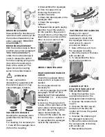
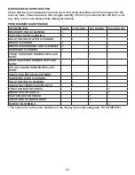
With the brushes base group 
in lifted position, insert the 
brushes into their plate seat 
underneath the brushes base 
turning them until the three 
metal buttons are properly 
seated in their slots; quickly 
rotate the brushes to push the 
button towards the coupling 
spring until they get blocked.  
The figure shows the rotating 
direction for brushes coupling.

Use only brushes supplied 
with the machine or the 
ones indicated in the 
paragraph “RECOMMENDED 
BRUSHES”.

 The use of other brushes can 
compromise the result.

DETERGENT SOLUTION 
TANK

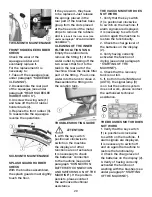
The capacity of the detergent 
solution tank is indicated in 
the technical data.
Open the screw plug placed 
in the left part of the machine 
and fill the detergent solution 
tank with clean water at a 
maximum temperature of 
122°F (50°C). Add the liquid 
detergent in the percentage 
and conditions recommended 
by the manufacturer. To avoid 
excessive foam, which could 
cause problems to the vacuum 
motor, use the minimum 
percentage of detergent. 
Screw down the plug to close 
the tank.

Summary of Contents for 99772

Page 1: ...RTH TX 76140 PHONE 800 VACUUMS FAX 817 551 0719 WWW TORNADOVAC COM Operations Maintenance Manual For Commercial Use Only Form No L9772 BA 06 20 Tornado Industries LLC All rights reserved BD 26 27 RIDE ON SCRUBBER MODEL NO 99772 Save These Instructions ...

Page 2: ...2 NOTES Within 30 days to activate the warranty go to https tornadovac com services warranty registration form aspx For warranty information go to www tornadovac com ...

Page 3: ...ing backwards 15 Working in automatic mode 15 Working in manual mode 16 Flow adjustment of detergent solution 17 Brush pressure adjustment 17 Electric protection 17 Overflow device 17 STOPPING MACHINE AFTER CLEANING 17 DAILY MAINTENANCE 18 Recovery tank emptying and cleaning 18 Suction filter cleaning 18 Brush cleaning 19 Squeegee cleaning 19 WEEKLY MAINTENANCE 19 Rear squeegee rubber check 19 Squ...

Page 4: ... ask you to read this instruction booklet carefully whenever difficulties arise in the course of the machine s use In case of need we ask you to contact our service department for all advice and servicing as may prove necessary TECHNICAL DESCRIPTION U M BD 26 27 Cleaning width in mm 26 660 Squeegee width in mm 33 835 Working capacity up to sq ft h sqm h 35 521 3300 Brushes diameter in mm 2 x 14 34...

Page 5: ...P UP DOWN SQUEEGEE 13 PUSH BUTTON VISUALIZATION HOUR METER DISPLAY 14 PUSH BUTTON VISUALIZATION BRUSHES PRESSURE SET DISPLAY 15 SIGNAL LAMP PARKING BRAKE ON 16 SIGNAL LAMP UP DOWN BRUSHES 17 PUSH BUTTON UP DOWN BRUSHES 18 SIGNAL LAMP STARTING BRUSHES ROTATION 19 PUSH BUTTON WATER OPENING SOLENOID VALVE 20 SIGNAL LAMP WATER OPEN SOLENOID VALVE 21 PUSH BUTTON FOR SPEED SELECTION 22 SIGNAL LAMP SELEC...

Page 6: ...RIVE WHEEL 14 ELECTRICAL LAYOUT COVER 5 CAP FOR DETERGENT SOLUTION 15 ACCELERATOR PEDAL 6 SUCTION HOSE 16 SOLUTION DRAIN PLUG 7 SUCTION COVER 17 DETERGENT SOLUTION OUTER FILTER 8 BLOCKING LEVERS SUCTION COVER 18 TRACTION MOTOR WHEEL 9 SQUEEGEE HOSE 19 BOTTOM PLATE 10 RECOVERY TANK HOSE PLUG 20 BRUSHES BASE GROUP 21 REAR WHEELS ...

Page 7: ...re extinguisher Do not use water Do not strike shelvings or scaffoldings where there is danger of falling objects Adapt the working speed to the conditions Do not use the machine on areas having a higher gradient than the one stated on the number plate The machine has to carry out simultaneously the operations of washing and drying Different operations must be carried out in restricted areas prohi...

Page 8: ...ymbol denoting the push button to visualize on the display the brush pressure set Symbol denoting the functioning of the adjustment knob of the brush pressure Symbol denoting the push button and the signal lamp up down of the squeegee Symbol denoting the crossed bin Indicates that at the end of its activity the machine has to be disposed conforming to the laws in force Symbol denoting the open boo...

Page 9: ... To do this keep the lever 3 lifted With the delivery of the machine we also supply a cord that permits the lever operation 3 After having moved the machine take off the cord and keep it for eventual re use When the parking brake is released manually for example when the machine has to be moved without batteries avoid covering slopes and do not park on them either 4 Move the machine backwards as i...

Page 10: ... create short circuit BATTERY CHARGER Make sure that the battery recharger is suitable for the installed batteries both for their capacities and type lead acid or GEL and equivalent This operation must be carried out by qualified staff A wrong or faulty cable connection can cause serious damages to persons or things In order not to cause permanent damage to the battery it is necessary to avoid the...

Page 11: ...e rotate the key switch clock wise Rotating it counterclockwise will turn off all functions see LEGEND PANEL OF CONTROLS WHEN THE MACHINE IS SWITCHED ON ON THE DISPLAY 1 APPEAR IN ORDER THE FOLLOWING INFORMATION 1 The machine model for example AdL 2 The setting of the battery check card which can be GE 24 check card set for AGM batteries or Pb 24 check card set for lead batteries ATTENTION ATTENTI...

Page 12: ...ckwise 5 Insert the squeegee hose 5 into its coupling as indicated in the figure ADJUSTMENT OF THE SQUEEGEE The lower part of the rubber is too much bent Take off the pressure rotating the wing nut 6 counterclockwise The lower part of the rubber is not much bent Increase the pressure rotating the wing nut 6 clockwise Check that the wheels which adjust the height do not rest on the floor in this ca...

Page 13: ... ring placed at the extremity of the metal strip still free Please act as above for both splash guard rubbers With the brushes assembled the splash guard must slightly touch the floor For the disassembly it is necessary to proceed inversely with above mentioned operations ATTENTION ATTENTION To carry out brushes assembly operations with the electric supply on may cause damages to hands With the br...

Page 14: ...f the batteries on the display 3 4 Pressing the push button 7 the functioning of BREAK WASHING is chosen and the transfer operations of the machine are carried out see under paragraph FORWARD AND BACKWARD MOVEMENT When the signal lamp 6 is on then the machine is in BREAK WASHING mode ATTENTION In manual mode every function of the machine has to be activated or deactivated manually FORWARD AND BACK...

Page 15: ...WARD MOVEMENT WORKING BRAKE To stop the machine during normal working situations it is sufficient to release the accelerator pedal because the machine has an electronic brake system To restart press again the accelerator pedal PARKING BRAKE The machine is equipped with a parking brake on the traction motor wheel that operates at the complete release of the accelerator pedal or when the machine is ...

Page 16: ...he washing with the brushes or only the drying of the floor 2 Pressing the push button 2 the functioning of manual MAN mode is chosen When the signal lamp 1 is on then the machine is functioning in manual MAN mode TO CARRY OUT THE WASHING WITH ONLY THE BRUSHES 1 Check that the knob of the solution valve 8 is in the position of optimum flow depending on the type of floor and the type of dirt see un...

Page 17: ...ENT OF THE DETERGENT SOLUTION To adjust the detergent solution quantity that flows down onto the brushes it is necessary to rotate the solution valve knob 1 placed on the right of the steering column rotating counterclockwise to increase it and clockwise to reduce it up to close the flow It is better to adjust the water flow during work and at every adjustment of the brushes pressure ADJUSTMENT OF...

Page 18: ...olution and recovery filters Squeegee with their rubbers and hoses Brushes must be carried out using gloves to protect from contact with dangerous solutions RECOVERY TANK EMPTYING AND CLEANING 1 Remove the exhaust hose 1 from the holding bracket 2 Remove the plug 2 from the exhaust hose by pulling on the lever 3 and empty the recovery tank into appropriate containers in compliance with the respect...

Page 19: ... jet 6 Reassemble all parts BRUSHES CLEANING Disassemble the brushes and clean them with a water jet for the brushes disassembly see under paragraph BRUSHES DISASSEMBLY ATTENTION To carry out brushes disassembly operations with the electric supply on may cause damages to hands SQUEEGEE CLEANING Keeping the squeegee clean guarantees the best drying result For cleaning it is necessary to 1 Take off ...

Page 20: ...o the solution tank TROUBLESHOOTING GUIDE If with the key switch positioned clockwise to switch on the machine the display and other functions are not activated it is necessary to check the batteries connection to the machine see under paragraph CONNECTION BATTERIES CONNECTION AND SWITCHING ON OF THE MACHINE If the problem persists please contact the authorized technical assistance THE VACUUM MOTO...

Page 21: ...THE SQUEEGEE 4 Check that the suction and the squeegee hoses are correctly inserted in their proper seats on the recovery tank 5 Clean the suction filter see under paragraph SUCTION FILTER CLEANING 6 Clean the squeegee hose see under paragraph SQUEEGEE HOSE CLEANING 7 Turn of replace the rubbers if worn out 4 If both in mode MAN and AUTO the signal lamp 3 is on but the brushes do not turn please c...

Page 22: ... 1000 HOURS RECOVERY TANK CLEANING SUCTION FILTER CLEANING SOLUTION TANK FILTER CLEANING BRUSH CLEANING BRUSH DISASSEMBLY AND CLEANING SQUEEGEE CLEANING FRONT SQUEEGEE RUBBER REPLACE MENT REAR SQUEEGEE RUBBER REPLACE MENT SPLASH GUARD RUBBER REPLACE MENT CHECK SQUEEGEE ADJUSTMENT SQUEEGEE HOSE CLEANING SOLUTION TANK CLEANING CHECK BATTERIES ELECTROLYTE TRACTION MOTOR CHECK BRUSH MOTOR CHECK SUCTIO...

Page 23: ...cker bristles creating brush vibration PAD HOLDER It is equipped with anchor points which permit the blocking of the abra sive pad during work The pad is recommended to clean smooth floors MACHINE CODE QTY DESCRIPTION USE BD 26 27 48903020 2 Brush PPL 0 6 Ø 345 Normal floors 48903030 2 Brush PPL 0 9 Ø 345 Smooth floors with small joints and persistent dirt 48903040 2 Brush TYNEX Ø 345 Floors of re...

Reviews: