background image

10

BEFORE USE

HANDLING OF THE PACKED MACHINE

The machine is supplied with suitable 

packing for fork lift truck handling.

The total weight is 1587 lbs.720 kg.

Packing dimensions:

Base: 84” x 50” 213 cm x 125 cm

Height: 65” 165 cm 


ATTENTION:

Do not place any packings on top.

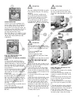
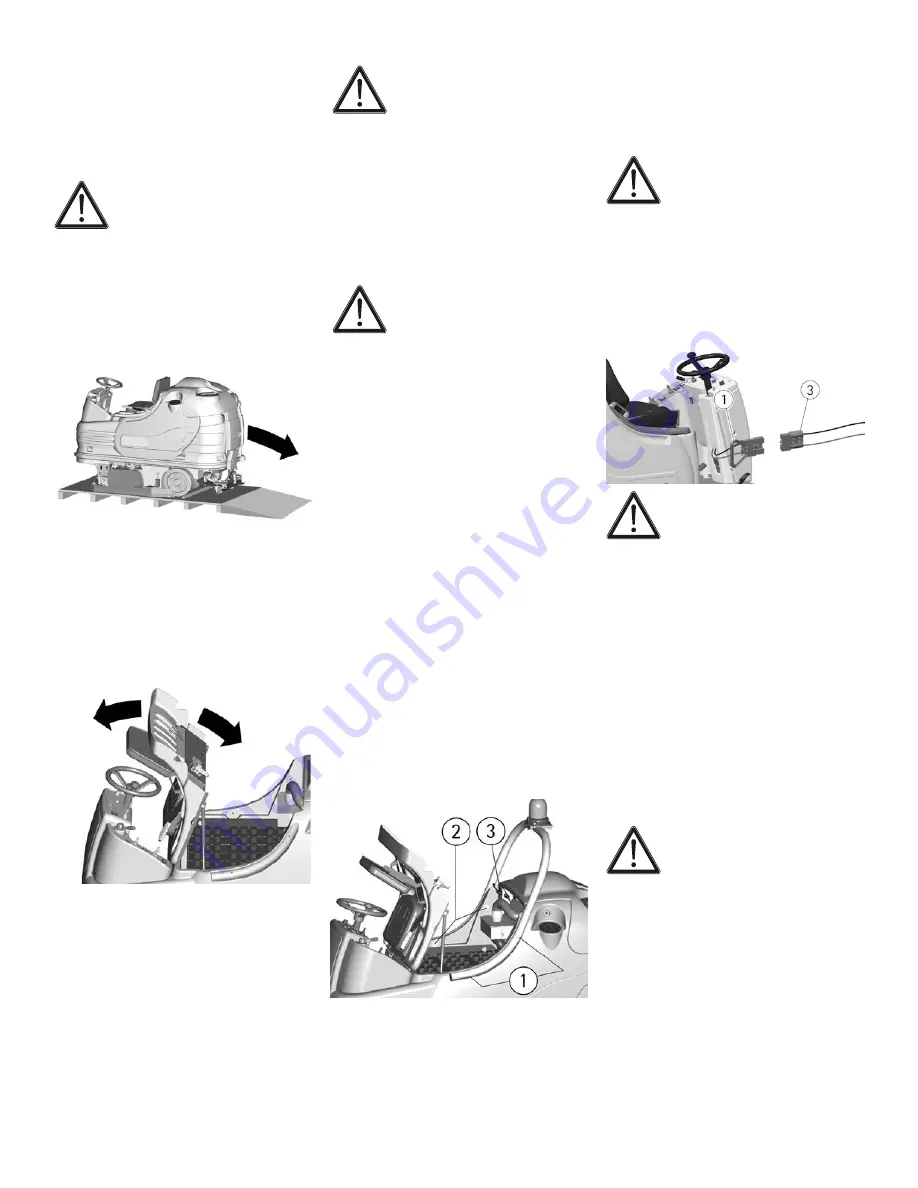
UNPACKING OF THE MACHINE

1. Remove the external packing.

2. Move the machine backwards, as 

indicated in the figure, avoiding heavy 

contacts to mechanical parts.

3. Keep the pallet for further transport.

ACCESS TO THE BATTERY COMPART-

MENT

1. Bring the machine on a level surface.

2. Rotate the seat platform forward up to 

the blocking of the support arm.

3. When completed, close the battery com-

partment, after releaseing the support arn, 

reposition the seat platform.

BATTERY INSTALLATION AND SETTING 

OF THE BATTERY TYPE

The machine is equipped either with bat-

teries in serial connection or elements of 

DIN-type assembled together and connect-

ed in series for a total of 36 Volt, placed 

in its appropriate compartment under the 

seat platform and must be handled using 

suitable lifting equipment (due to weight, 

considering the type of batteries chosen, 

and coupling system).

The batteries must be in accordance with 

CEI 21-5 Norms. 

 ATTENTION:

The machine and its battery check card 

are factory set for the use of traditional 

lead batteries.

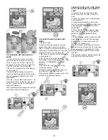
CHECK THE SETTING OF THE CHECK 

CARD 

(see under paragraph "

BATTER-

IES CHARGE LEVEL INDICATOR"

).

In case of GEL batteries installation, it is 

necessary to set the battery check card. 

Please contact the authorized technical 

assistance.

 ATTENTION:

Strictly follow manufacturer/distributor 

indications for the maintenance and re-

charge of the batteries. All installation and 

maintenance operations must be executed 

by specialized staff, using suitable protec-

tion accessories.

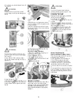
For batteries installation it is necessary to 

reach the battery compartment as indi-

cated under paragraph “ACCESS TO THE 

BATTERY COMPARTMENT”.

1. Place the batteries in its compartment.

2. 

Connect the terminals, respecting the 

polarities, avoiding contact with other 

parts that could create short circuit.

ASSEMBLING OF THE ROLLBAR

For packing reasons the support of the 

blinking light is supplied disassembled.

Proceed as follows:

1. Take off the four fixing screws (1) from 

the rollbar.

2. Place the rollbar into their seats (2) on 

the tank.

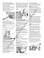
3. Fasten the screws passing them in the 

same order in their holes foreseen on the 

support.

4. Complete the assembly connecting the 

connectors (3) to supply the blinking light 

and the working lights (optional).

BATTERY CHARGER

Make sure that the battery charger is 

suitable for the installed batteries both 

for their capacities and type (lead/acid 

or GEL and equivalent).

In the plastic bag containing the use and 

maintenance you will find the coupling 

connector for the charger. It must be as-

sembled onto the cables of your charger, 

following the instructions given by the 

manufacturer. 

 ATTENTION:

This operation must be carried out by 

qualified staff. A wrong or faulty cable 

connection can cause serious damages to 

persons or equipment.

BATTERIES RECHARGING

1. Plug the connector (3) of the battery 

charger into the battery connector.

2. Proceed with the charging.


ATTENTION:

Never charge a GEL battery with a non 

suitable charger. Strictly follow the 

instructions supplied by the batteries 

and charger manufacturer.

In order not to cause permanent damages 

to the batteries, it is necessary to avoid 

their complete discharge, providing for the 

charging within a few minutes after the 

batteries discharge signal starts blinking.

NOTE: Never leave the batteries com-

pletely discharged even if the machine is 

not used. In case of traditional batteries, 

please check the electrolyte level every 20 

charging cycles and eventually top them 

up with distilled water. Never leave the 

batteries discharged for more than two 

weeks. 


ATTENTION:

For the recharge of the batteries it is nec-

essary to follow strictly all the indications 

given by the manufacturer/distributor. All 

the installation and maintenance opera-

tions must be carried out by qualified staff. 

Danger of gas exhalations and emis-

sion of corrosive liquids. Fire danger: 

do not approach with free flames.

BATTERIES DISPOSAL

It is compulsory to hand over exhausted 

batteries, classified as dangerous waste, 

to an authorized institution according to 

the current laws.

https://harrissupplyind.com - To Order Parts Call 608-268-8080

Summary of Contents for 99795

Page 1: ...17 551 0719 WWW TORNADOVAC COM Operations Maintenance Manual For Commercial Use Only BR 40 66 RIDE ON SCRUBBER MODEL NO 99795 Form No L9795AB 02 17 Tornado Industries LLC All rights reserved h t t p s h a r r i s s u p p l y i n d c o m T o O r d e r P a r t s C a l l 6 0 8 2 6 8 8 0 8 0 ...

Page 2: ... 1 Except all Windshears Blowers Storm TV2SS Side and Downdraft Insulation Blowers CV 30 CV 38 CK14 1 PRO CK 14 2 PRO SWM 31 9 CK LW13 1 CK LW 13 1 ROAM CV 38 48 Dual PV6 PV10 PV6 ROAM Wall Mount Vacuum and all chargers are warranted for 1 one year for both parts and labor 2 All non wear item parts purchased after warranty expiration are warranted for 90 days 3 Warranty starts from the date of sal...

Page 3: ...3 NOTES h t t p s h a r r i s s u p p l y i n d c o m T o O r d e r P a r t s C a l l 6 0 8 2 6 8 8 0 8 0 ...

Page 4: ...al mode 15 Side brush 16 Working adjustments 16 Flow adjustment of the detergent solution 16 Adjustment of the brushes pressure 16 Electric protection 16 Overflow device 17 STOP OF THE MACHINE AFTER CLEANING OPERATION 17 DAILY MAINTENANCE 17 Recovery tank emptying and cleaning 17 Emptying and cleaning of the collection box 17 Suction filter cleaning 18 Brushes cleaning 18 Squeegee cleaning 18 WEEK...

Page 5: ...E OF FUNCTIONING 13 SWITCH SIDE BRUSH ACTIVATED 14 SELECTOR UP DOWN BRUSHES 15 SELECTOR UP DOWN SQUEEGEE 16 SWITCH SUCTION MOTORS 17 SIGNAL LAMP PARKING BRAKE ON 18 SIGNAL LAMP SUCTION MOTORS ON 19 SIGNAL LAMP DETERGENT SOLUTION LOW 20 SIGNAL LAMP RECOVERY TANK FULL 21 SIGNAL LAMP SQUEEGEE DOWN 22 SIGNAL LAMP BRUSHES DOWN 23 SIGNAL LAMP BRUSHES ROTATION 24 SIGNAL LAMP WATER OPEN SOLENOID VALVE 25 ...

Page 6: ... HOSE RECOVERY TANK 11 EXHAUST HOSE RECOVERY TANK 11 EXHAUST HOSE RECOVERY TANK 12 SQUEEGEE ASSEMBLY 13 PANEL CONTROLS 14 LEVER BLOCK RELEASE PARKING BRAKE 15 COVER ELECTRICAL LAYOUT 16 BUMPER 17 PEDAL ACCELERATOR 18 TRACTION MOTOR WHEEL 19 SIDE BRUSH 20 BOTTOM PLATE 21 BRUSHES BASE GROUP 22 REAR WHEELS h t t p s h a r r i s s u p p l y i n d c o m T o O r d e r P a r t s C a l l 6 0 8 2 6 8 8 0 8...

Page 7: ... II km h mph 4 5 7 2 7 4 3 Maximum gradient 10 Solution tank l gal 235 62 Recovery tank l gal 250 66 Machine length mm in 2025 80 Machine height without rollbar mm in 1330 53 Machine height with rollbar and without blinking light mm in 1795 71 Machine height with rollbar and blinking light mm in 1965 77 Machine width without squeegee mm in 1165 46 Machine width with side brush in operating positio...

Page 8: ...s for example hydrocarbons ashes or soot In case of fire use a powder fire extinguisher Do not use water Do not strike shelvings or scaf foldings where there is danger of falling objects Adapt the working speed to the adhesion conditions particu larly slow down before narrow curves have to be faced Do not use the machine on areas having a higher gradient than the one stated on the num ber plate Th...

Page 9: ... the adjust ment selector of the brushes pressure Symbol denoting the acti vation and the signal lamp squeegee down Symbol denoting the acti vation of the squeegee up Symbol denoting the switch and the signal lamp of the functioning of the suction motors Symbol denoting the charge level of the batter ies Symbol denoting the push button to visualize the hour meter on the display Symbol denoting the...

Page 10: ...king reasons the support of the blinking light is supplied disassembled Proceed as follows 1 Take off the four fixing screws 1 from the rollbar 2 Place the rollbar into their seats 2 on the tank 3 Fasten the screws passing them in the same order in their holes foreseen on the support 4 Complete the assembly connecting the connectors 3 to supply the blinking light and the working lights optional BA...

Page 11: ...its position as indi cated in the figure ADJUSTMENT OF THE SQUEEGEE In order to have a perfect drying result through the squeegee the rear rubber must have the lower bending uniformly ad justed in all its length For the adjustment the suction motor has to be switched on and the brushes have to function together with the detergent solution If the lower part of the rubber is bent too much Take off t...

Page 12: ... the machine see under para graph STARTING OF THE MACHINE positioning the selector 12 to the right to choose the manual mode MAN 3 Activate the selector 14 of up down of the brushes base to lower the brushes Once that it is lowered the brushes begin to turn 4 Turn the key counterclockwise to turn off the machine ATTENTION To carry out brushes assembly operations with the electric supply on may cau...

Page 13: ...upper part of the tank is well closed Finally verify the correct tightening of the closing lever 5 of the cleaning door 6 placed in the lower part of the tank DETERGENT SOLUTION TANK The capacity of the detergent solution tank is indicated in the technical data Open the screw plug placed in the left part of the machine and fill the detergent solu tion tank with clean water at a maximum temperature...

Page 14: ...th an auto matic system that reduces the speed when the drive direction is changed The speed reduction is higher as the curve is sharper The speed returns again normally as soon as the machine gets out from the curve and it runs along straight paths HORN The machine is equipped with a horn which is activated pressing the push button 6 WORKING BRAKE The machine is equipped with a hydrau lic braking...

Page 15: ...per use of the machine see under paragraph GENERAL RULES OF SECURITY If they are carried out separately it is necessary to forbid the working areas to the passage of non au thorized personnel and to signal the areas of moist floors with suitable signs Activate the machine see under para graph STARTING OF THE MACHINE positioning the selector 12 to the right to choose the manual mode MAN TO CARRY OU...

Page 16: ...ced under the frame near the brush itself Please remember that the side brush does not have a scrubbing function but simply moves the dirt towards the center of the machine ADJUSTMENT OF THE BRUSHES PRESSURE Both in automatic and in manual mode it is possible through the selector 4 to adjust the brushes pressure on the floor in eight established levels During the operation youcan visualize on the ...

Page 17: ...owing components that are in contact with liquids and there fore solution and recovery tanks collection box solution and recovery filters squeegee with their rubbers and hoses brushes must be carried out using gloves to protect from contact with dangerous solutions RECOVERY TANK EMPTYING AND CLEANING 1 Hold the exhaust hose 1 placed in the rear part of the machine after having taken it off from it...

Page 18: ...the brushes and clean them with a water jet for the brushes disas sembly see under paragraph BRUSHES ASSEMBLY AND DISASSEMBLY and SIDE BRUSH ASSEMBLY AND DISAS SEMBLY ATTENTION To carry out brushes disassembly op erations with the electric supply on may cause damages to hands SQUEEGEE CLEANING Keeping the squeegee clean guarantees the best drying result For cleaning it is necessary to 1 Take off t...

Page 19: ...splash guard of the side brush must slightly touch the floor If the rubber is worn it has to be replaced The device has to be in rest position at machine stop ATTENTION To carry out above operations with the electric supply on may cause damages to hands To replace the rubber 1 Take off the side brush see under paragraph SIDE BRUSH ASSEMBLY AND DISASSEMBLY 2 Take off the screws 1 that block the rub...

Page 20: ...ing brake is not applied see under paragraph EMERGENCY PARKING BRAKE 5 Check that the selector 8 is in the movement position 6 Press the accelerator pedal placed on the right side to start the machine If the problem persists please contact the authorized technical assistance THE WATER DOES NOT COME DOWN ONTO THE BRUSHES OR IS INSUFFI CIENT 1 Verify that the key switch 5 is posi tioned clock wise t...

Page 21: ... that the recovery tank is not full 2 Check that the squeegee rubbers are clean see under paragraph SQUEEGEE CLEANING 3 Check the adjustment of the height and the inclination of the squeegee see under paragraph ADJUSTMENT OF THE SQUEEGEE 4 Check that the suction and the squee gee hoses are correctly inserted in their proper seats on the recovery tank 5 Clean the suction filter see under paragraph ...

Page 22: ... is hygroscopic It looses its physical characteristics over the time TYNEX Nylon bristles with grains of abrasive material Use with caution in order not to mark the floor or ruin the polishing BRISTLES THICKNESS Thicker bristles are more rigid and must be used on smooth floor or floor with small joints On irregular floors with deep joints or relieves it is recommended to use softer bristles which ...

Page 23: ...23 h t t p s h a r r i s s u p p l y i n d c o m T o O r d e r P a r t s C a l l 6 0 8 2 6 8 8 0 8 0 ...

Page 24: ...e feet meters Total Hard Floor Area Total Carpeted Area Square feet square meters o Contacted by local dealer o Previous experience with Tornado products o Reputation Recommendation o Advertising o Direct mail o Internet o Other o 0 10 000 0 930 o 10 50 000 930 4 650 o 50 250 000 4 650 23 250 o Over 250 000 over 23 260 o 0 10 000 0 930 o 10 50 000 930 4 650 o 50 250 000 4 650 23 250 o Over 250 000...

Reviews: