11
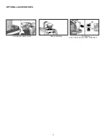
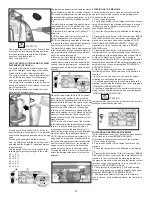
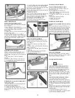
The bending is not uniform
Adjust the squeegee inclination rotating counter-
clockwise the wing nut (7) to increase the bending
in the central part, or clockwise to increase the
bending on the extremities.
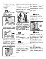
Height adjustment
Once that the pressure and inclination of the
squeegee have been adjusted, it is necessary to
fix this optimum condition making touch slightly
the wheels onto the floor. Rotate counterclockwise
the registers (8) to lower the wheels or clockwise
to raise them. Both wheels must be adjusted in
the same measure.
ATTENTION:
Every type of floor requires a specific adjustment.
For example, concrete floors (where the friction
results to be high) need little pressure, while
smooth floors (ceramics) need higher pressure.
If the cleaning operations are made always on the
same type of floor, the adjustment can change
only in function of the rubber wear.
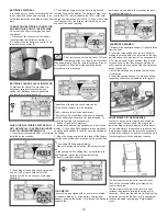
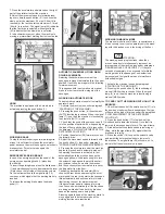
ADJUSTMENT HEIGHT SIDE RUBBERS
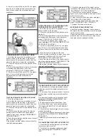
To adjust the side rubbers, it is necessary to act
upon the adjusting screws (1) and (2) after having
loosened the upper blocking nuts. Unscrewing,
the rubber lowers, while screwing down, the rub-
ber is lifted. The reason of the adjustment is to
obtain an uniform bending.
Having finished the adjustment, tighten the block-
ing nuts to fix the position.
BRUSHES ASSEMBLY AND DISASSEMBLY
Normally, the machine is delivered with the
brushes assembled.
To assemble and disassemble the brushes on
both sides of the machine:
1. Make sure the machine is switched off and with
the brushes base in up position (lifted).
ATTENTION:
To carry out brushes assembly operations with
the electric supply on, may cause damages to
hands.
ATTENTION:
This operation must be carried out using gloves
to protect from contact with dangerous solutions.
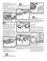
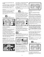
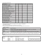
2. Unblock the bar of the side rubber after having
released the knob (1).
3. Open the bar of the side rubber (2) as shown
in the figure.
4. Extract the support plate (3) of the brushes
pulling it outwards by holding its handle.
5. Extract the brush (4).
6. During the reassembly of the brush (4), insert
it into the brush base from the part where the
seat is deeper (about 1.5” (40mm)). The opposite
part with a depth of about .5” (13,5mm) has to
look towards the support plate.
7. Place the support plate (3) into its position, then
put back the bar of the side rubber (2) blocking it with
the knob (1).
ATTENTION:
The brushes must be inserted easily without using
tools in order not to damage or force them.
Use only brushes supplied with the machine or the
ones indicated in the paragraph “RECOMMENDED
BRUSHES”. The use of other brushes can compro-
mise the good washing result.
FLOOR CLEANING
RECOVERY TANK
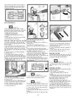
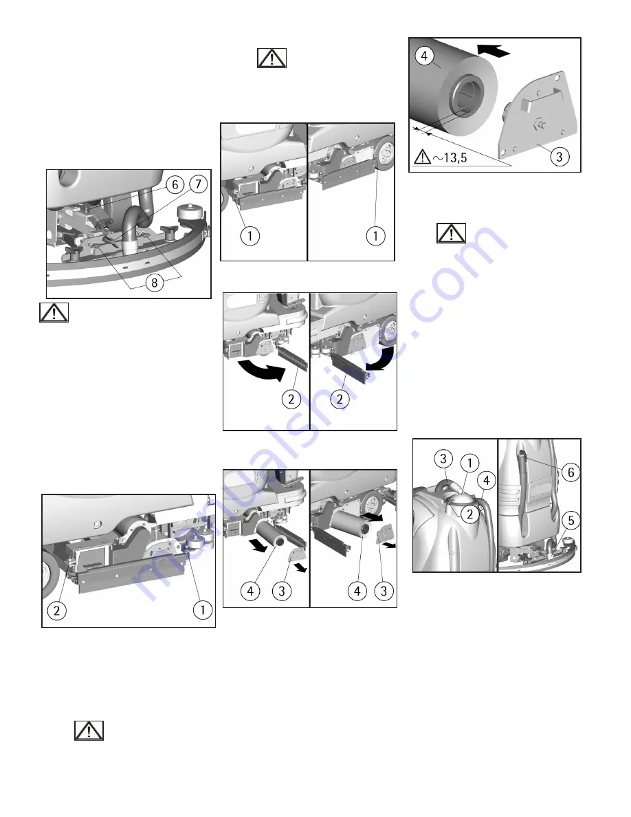
Check that the cover of the suction filter (1) is cor-
rectly secured, after rotating the levers (2) and that
the suction motor hose (3) is correctly connected to
it.
Verify also that the squeegee hose couplings (4/5)
are correctly inserted into their seats and that the
exhaust hose plug (6) placed in the rear part of the
machine is well closed.
DETERGENT SOLUTION TANK
The capacity of the detergent solution tank is indi-
cated in the technical data.
Open the screw plug placed in the left part of the ma-
chine and fill the detergent solution tank with clean
water at a maximum temperature of 50°C (122°F).
Add the liquid detergent in the percentage and condi-
tions foreseen by the manufacturer. To avoid exces-
sive foam presence, which could cause problems to
the suction motor, use the minimum percentage of
detergent. Screw down the plug to close the tank.
Summary of Contents for BR 28/27
Page 2: ...2...
Page 3: ...3 NOTES...


