


12
ATTENTION:
Use always low foam detergent. To avoid foam
pres¬ence, before starting working operation,
introduce into the recovery tank a minimum
quantity of anti-foam product.
Never use pure acid.
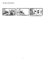
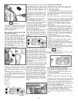
3SD SYSTEM SOLUTION SAVING SYSTEM
DISPENSER (OPTIONAL)
The system permits the predetermined dos-
ing of the detergent percentage which will be
mixed with the water of the solution tank.
The system consists of a dual hydraulic circuit,
one for the water and one for the detergent,
each one equipped with a suitable pump.
The detergent is contained in a tank with a ca-
pacity of 2 gallons (8 litres), placed in the front
part of the machine.
The tank is transparent, to enable the visual-
ization of the detergent level.
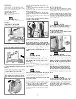
Pressing once the push button (A) on the in-
strument board, on the display (1) the indicator
shows the detergent percentage which is being
used.
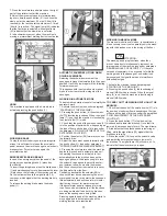
Pressing the same push button in succes-
sion, six different possibilities of setting can be
selected and the display (1) visualizes always
the percentage.
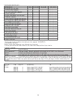
The indication of the level corresponds to the
following detergent percentages in the water:
d0 = 0 %
d1 = 0,3 %
d2 = 0,6 %
d3 = 1,2 %
d4 = 2,4 %
d5 = 4,5 %
The last dosing adjustment set remains stored
by the system also with the machine stopped.
The dosing adjustment can be made only with
the brushes moving (during operation), so that
the dosing ratio cannot be modified acciden-
tally.
The water flow is adjusted through the 8-way
commutator (B): one OFF position and 7 op-
erating positions from a minimum of .3 gallon
(1,2 litres)/min to a maximum of 1 gallon (3,7
lit)res/min.
In OFF position both the water flow and its
relative detergent flow is interrupted.
NOTE: the detergent percentage in the water
is in any case always constant independently
from the level course of the water set.
The water flow, besides from being connected
to the set position through the commutator, is
also proportional to the machine speed (posi-
tion of the accelerator pedal).
In this way, having to reduce the speed near
curves or in presence of difficult areas, a
useless water waste is avoided and simulta-
neously the drying is improved, because the
squeegee picks up always the same solution
quantity.
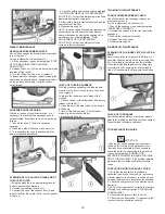
When the commutator (B) is in OFF position,
an auxiliary water system can be activated,
that permits the traditional use of the machine
and therefore the filling of the solution tank with
water and detergent without using the system
and therefore without the use of the pumps.
In this case it is necessary to open and adjust
manually a solution valve (C) placed un-der the
machine. In this situation the push button (A)
handles the command of the solenoid valve in
manual function.
NOTE: at the end of each use of the machine
in the traditional mode (without dosing system),
to return to use the dosing system again, it
is necessary to close the solution valve (C),
otherwise the proportions water and detergent
are not anymore the predetermined ones.
NOTE: if the automatic dosing system is not
being used for a long time, it is possible that
the hoses of the detergent circuit are emptied
and therefore at the first use, the detergent
begins to come out onto the brushes with a
certain delay compared to the water outlet.
Through the solution valve (D) it is possible to
empty the detergent tank and to recover the
detergent.
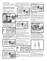
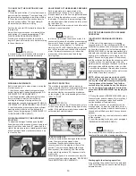
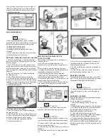
STARTING OF THE MACHINE
A safety device avoids the machine’s movement if the
operator is not seated correctly on the guiding place.
To switch on the machine:
1. Sit on the guiding place.
2. Turn the key switch (24) clockwise to switch on the ma-
chine. Automatically, the machine gets ready in manual
(MAN) mode and in forward movement with the quick
speed (signal lamp 22).
3. Check the charge level of the batteries on the display
(1).
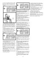
4. Pressing the push button (5) the functioning of BREAK
WASHING is chosen and the transfer operations of the
machine are carried out (see under paragraph “FOR-
WARD AND BACKWARD MOVEMENT"). When the
signal lamp (4) is on, then the machine is in BREAK
WASHING mode.
5. Pressing the push button (6) the automatic (AUTO)
functioning is chosen, while pressing the push button (3),
the functioning of the machine becomes manual (MAN).
A. When the signal lamp (7) is on, the machine is
functioning in automatic (AUTO) model and the machine
activates and deactivates all the working functions in an
automatic mode (see under paragraph “WORKING IN
AUTOMATIC MODE”).
B. When the signal lamp (2) is on, the machine is
functioning in manual (MAN) mode and it is possible to
choose if:
I. to carry out the only transfer of the machine without
activating or deactivating the working functions.
II. to activate separately only the controls relative to the
washing function with the brushes (see under paragraph
“WORKING IN MANUAL MODE”).
III. to activate separately only the controls relative to the
drying function with the squeegee (see under paragraph
“WORKING IN MANUAL MODE”).
ATTENTION:
In manual mode every function of the machine has to be
activated or deactivated manually.
FORWARD AND BACKWARD MOVEMENT
It is recommended to carry out always the mere transfer
of the machine in mode (BREAK WASHING).
To proceed to activate the movement of the machine:
1. Sit on the guiding place.
2. Turn the key switch (24) clockwise to switch on the
machine.
3. Check the charge level of the batteries on the display
(1).
4. Pressing the push button (5) the functioning of BREAK
WASHING is chosen to carry out the mere transfer of the
machine. In fact, in this mode the washing functions of
the machine are not working and only the traction system
functions. When the signal lamp (4) is on, then the ma-
chine is in BREAK WASHING mode.
5. Check through the signal lamp (15) that the parking
brake is not inserted and eventually release it (see under
paragraph EMERGENCY-PARKING BRAKE”).
6. Positioning the selector (28) forward, the forward
drive is chosen, while positioning it back, the rear drive is
chosen.
Summary of Contents for BR 28/27
Page 2: ...2...
Page 3: ...3 NOTES...


