

14
TO CARRY OUT THE FUNCTION OF ONLY
DRYING:
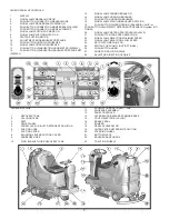
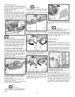
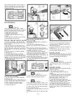
1. Press the push button (11) of up/down squee-
gee to lower the squeegee. The signal lamp (12)
indicates that the squeegee is lowering or lifting.
2. Press the switch (9) of the suction motor to
start the suction system. The signal lamp (8)
indicates that the machine is drying.
Position the selector (28) forward to choose the
forward drive.
Adjust the movement speed in forward with the
push button (21) (see under paragraph "FOR-
WARD AND BACKWARD MOVEMENT”).
Pressing the accelerator pedal, the machine
begins to proceed forward and to work according
to the set functions.
ATTENTION:
In manual mode every function of the machine
has to be activated or deactivated manually.
WORKING ADJUSTMENTS
Both in automatic as in manual mode, during the
first metres check:
1. that the squeegee adjustment guarantees a
perfect drying result (see under paragraph “AD-
JUSTMENT OF THE SQUEEGEE”).
2. that the adjustment of the detergent solution
flow is sufficient to wet the floor uniformly
avoiding the leakage of detergent from the
splash guards (see under paragraph “FLOW AD-
JUSTMENT OF THE DETERGENT SOLUTION”).
3. that the brushes pressure permits an efficient
washing action in function of the dirt and the
speed (see under paragraph “ADJUSTMENT OF
THE BRUSHES PRES-SURE”).
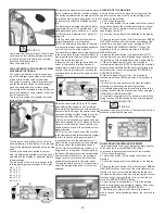
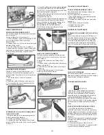
FLOW ADJUSTMENT OF THE DETERGENT
SOLUTION
To adjust the detergent solution quantity that
flows down onto the brushes it is necessary to act
upon the solution valve knob (27) placed on the
right of the steering column, rotating counterclock-
wise to increase it and clockwise to reduce it up
to close the flow.
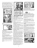
ADJUSTMENT OF THE BRUSHES PRESSURE
Both in automatic as in manual mode it is
possible through the knob (10) to adjust the
brushes pressure on the floor in eight established
levels. During the operation, we can visualize on
the display (1) the value in per percentage of the
electric absorption of the brushes motor by press-
ing the button (14).
The adjustment in this mode is done both in auto-
matic and manual operation.
ATTENTION:
In order not to overload the brushes motor, it is
convenient to reduce the brushes pressure going
from smooth floors to rough ones (ex. concrete).
The presence on the display (1) of a blinking
warning from P2 to P8 indicates that the pressure
level set determines an overload of the brushes
motor. It is therefore necessary to reduce the
pressure up to the level where the blinking
warning stops.
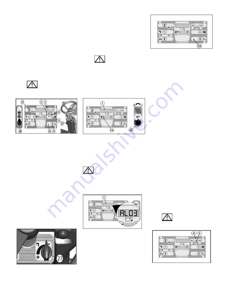
ELECTRIC PROTECTION
The machine is equipped with an electronic
system of protection for all components that carry
out functions of power or control. This device
blocks the defective component and indicates
on the display (1) the corresponding alarm from
”AL01” to “AL20”.
ATTENTION:
To restore the functioning of the component, turn
off and on again the machine acting upon the key
switch. If the problem persists, please contact the
authorized technical assistance.
OVERFLOW DEVICE
In order to avoid serious damages to the suction
motor, the machine is equipped with a
mechanical float that intervenes when the
recovery tank is full, closing the air flow of the
suction. The machines equipped with electric
float (optional), the switching off of the suction
motor and its signal lamp (12) happens in auto-
matic mode.
When this happens, it is necessary to empty the
recovery tank (see under paragraph “RECOVERY
TANK EMPTYING AND CLEANING”).
STOP OF THE MACHINE AFTER CLEANING
OPERATION
IN AUTOMATIC OR MANUAL WORKING
MODE:
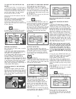
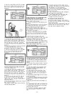
1. A the end of the washing cycle, pressing
the push button (5), the functioning of BREAK
WASHING is chosen. When the signal lamp (4) is
on, then the machine is in the functioning mode
BREAK WASHING. In this way automatically the
solenoid valve shuts down, the brushes are lifted
slightly (a few millimeters) continuing to turn for
about 10 seconds (drying phase of the brushes)
and the collection box drains the exceeding water
to the floor; then, the washing group lifts com-
pletely while the squeegee continues to remain in
working position with the suction motor on, after
5 seconds the squeegee lifts and when it reaches
the highest position, also the suction motor stops,
with a delay of another 5 seconds.
NOTE: all these phases are carried out with
the machine operating, so that the squeegee
can dry the interested cleaning area from the
“drying phase of the brushes” and further-
more can dry the suction hose of its dirty wa-
ter. At any time it is possible to interrupt the
proce-dure BREAK WASHING by stopping the
drive.
2. During the phase of BREAK WASHING, when
the accelerator pedal is released for more than 3
seconds, the squeegee raises itself and the
suction switches off automati-cally.
3. After three seconds, the accelerator can be
pressed again, if a machine's transfer has to be
made (you can anyway make the transfer even if
the pedal is not lifted once that 20 seconds have
passed).
4. Turn the switch key counterclockwise to switch
off the machine.
5. Insert the parking brake (see under paragraph
“EMERGENCY-PARKING BRAKE”).
ATTENTION:
The mode (BREAK WASHING) is specific for the
transfer at the end of the cleaning operation.
Starting again the cleaning operation:
A. by pressing the push button (6) the automatic
(AUTO) functioning is chosen to start working in
automatic mode.
Summary of Contents for BR 28/27
Page 2: ...2...
Page 3: ...3 NOTES...


