9
BEFORE USE
HANDLING OF THE PACKED MACHINE
The machine is supplied with suitable packing
foreseen for fork lift truck handling.
The total weight is 644 lbs.
Packing dimensions:
Base: 70” x 37” (178 cm x 93 cm)
Height: 55” (138 cm)
ATTENTION:
Do not place more than 2 packings on top of
each other.
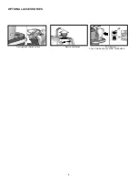
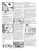
UNPACKING OF THE MACHINE
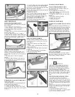
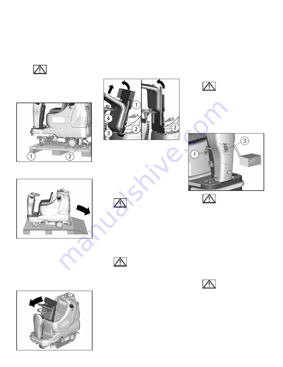
1. Remove the external packing.
2. Unscrew the brackets (1+2) that secure the
machine to the pallet.
3. Move the machine backwards, as indicated in
the figure, avoiding heavy contacts to mechani-
cal parts.
4. Keep the pallet and the brackets for eventual
transport.
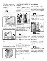
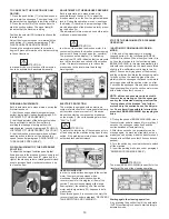
ACCESS TO THE BATTERY COMPARTMENT
1. Bring the machine on a level surface.
2. Rotate the seat platform forward and hook the
bar.
Having finished any intervention, to close the
battery compartment, reposition the seat plat-
form.
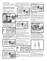
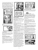
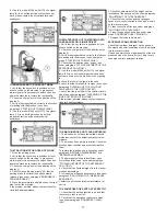
To install into the compartment a battery box, it is
necessary to:
1. Rotate the seat platform forward and hook the bar
(2) into position A.
2. Remove the holder (1) by unscrewing the two wing
nuts under the platform.
3. Pull outwards the releasing lever (3) of the seat
making slide the seat body (4) up to the highest posi-
tion.
4. Rotate further the platform in order to hook the bar
(2) into position B.
In this way it will be possible to handle the batteries
with suitable lifting equipment.
BATTERY INSTALLATION
The machine is equipped either with batteries in se-
rial connection or elements of DIN-type assembled
together and connected in series for a total of 24 Volt,
placed in its appropriate compartment under the seat
platform and must be handled using suitable lifting
equipment (due to weight, considering the type of bat-
teries chosen, and coupling system).
The batteries must be in accordance with CEI 21-5
Norms.
ATTENTION:
The machine and its battery check card foresee the
use of traditional lead batteries.
CHECK THE SETTING OF THE CHECK CARD (see
under paragraph "BATTERIES CHARGE LEVEL
INDICATOR").
In case of GEL batteries installation, it is necessary to
MODIFY THE SETTING of the electronic check card
(see under paragraph SETTING OF THE BATTERY
CHECK CARD”).
ATTENTION:
Strictly follow manufacturer/distributor indications for
the maintenance and recharge of the batteries. All
installation and maintenance operations
must be executed by specialized staff, using suitable
protection accessories.
For batteries installation it is necessary to reach the
battery compartment as indicated under paragraph
“ACCESS TO THE BATTERY COMPARTMENT”.
1. Place the batteries in its compartment.
2. Connect the terminals, respecting the polarities,
avoiding contact with other parts that could create
short circuit.
BATTERY RECHARGER
Make sure that the battery recharger is suitable
for the installed batteries both for their capacities
and type (lead/acid or GEL and equivalent).
In the plastic bag containing the use and mainte-
nance you will find the coupling connector for the
recharger. It must be assembled onto the cables
of your recharger, following the instructions given
by the manufacturer.
ATTENTION:
This operation must be carried out by qualified
staff. A wrong or faulty cable connection can
cause serious damages to persons or things.
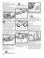
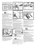
BATTERIES RECHARGING
1. Plug the connector (3) of the battery recharger
into the battery connector (1).
2. Proceed for the recharging.
ATTENTION:
Never charge a GEL battery with a non suitable
recharger. Strictly follow the instructions supplied
by the batteries and recharger manufacturer.
In order not to cause permanent damages to the
batteries, it is necessary to avoid their complete
discharge, providing for the recharging within a
few minutes after that the batteries discharge
signal starts blinking.
NOTE: Never leave the batteries completely
discharged even if the machine is not used. In
case of traditional batteries, please check the
electrolyte level every 20 recharging cycles and
eventually top them up with distilled water. Never
leave the batteries discharged for more than two
weeks.
ATTENTION:
For the recharge of the batteries it is necessary
to follow strictly all the indications given by the
manufacturer/distributor. All the installation and
maintenance operations must be carried out by
qualified staff. Danger of gas exhalations and
emission of corrosive liquids. Fire danger: do not
approach with free flames.
Summary of Contents for BR 28/27
Page 2: ...2...
Page 3: ...3 NOTES...


