


11
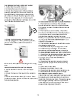
SPLASH GUARD ASSEMBLY
The two splash guards have to be assembled
onto the brush base group. Insert the metal
strips inside the suitable slots present on
the rubber. Place the round hole at the flat
extremity of the strip onto the screw placed in
the front part of the brush base group. Secure
the strips through the nut blocking it.
Screw down the knobs in the rear part of the
cover in the free extremity of the metal strips.
The operation has to be carried out for both
splash guards. With the brush assembled, the
splash guard must slightly touch the floor.
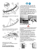
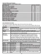
BRUSH ASSEMBLY
1. Take off the electric supply to the brush
motor unplugging the batteries connector (1).
2. Acting upon the pedal (8) lift the brush base
group.
3. With the brush base group in lifted position,
insert the brush into its plate seat underneath
the brush base turning it until the three metal
buttons are properly seated in their slots; rotate
quickly the brush to push the button towards
the coupling spring until it gets blocked. The
figure shows the rotating sense for the brush
coupling.
Use only brushes supplied with the machine
or the ones indicated in the paragraph
“RECOMMENDED BRUSHES”. The use of
other brushes can compromise the security.
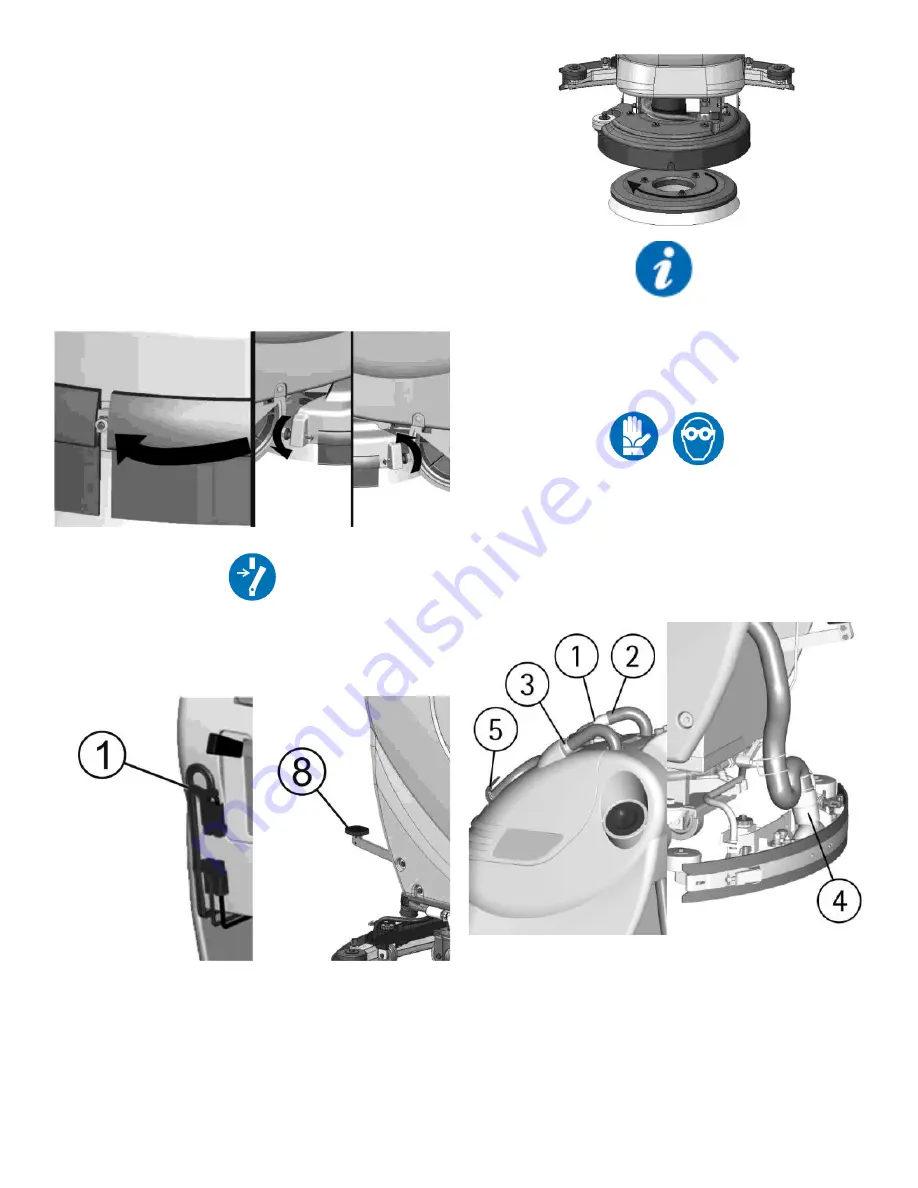
RECOVERY TANK
Check that the cover of the suction filter (1)
is correctly secured, after rotating the levers
and that the suction motor hose (2) is correctly
connected. Verify also that the squeegee hose
is correctly inserted into the seats (3 and 4) and
that the exhaust hose plug (5) placed in the
front part of the machine, is closed.
DETERGENT SOLUTION TANK
The solution tank is provided with an inspection
opening. This permits cleaning of the detergent
solution. Be sure that the cap is well tightened
after the cleaning.
Summary of Contents for TS120-S53-U
Page 20: ...20...


