background image

8

BEFORE USE
HANDLING OF THE PACKED MACHINE

The machine is supplied with suitable packing 
foreseen for fork lift truck handling.
The total weight is 205 lbs. (95 kg).
Packing dimensions:
Base: 46” x 26” (118 cm x 67 cm).
Height: 47” (119 cm).

Do not place more than 2 packings on top of 
each other.

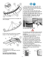
UNPACKING OF THE MACHINE

1. Remove the external packing.
2. Unscrew the brackets that secure the 
machine to the pallet.
3. Move the machine backwards, as indicated 
in figure, avoiding heavy contacts to 
mechanical parts.
4. Keep the pallet for eventual transport.

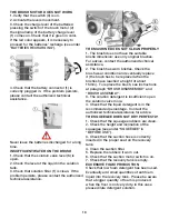
BATTERY INSTALLATION AND SETTING OF 
THE BATTERY TYPE

This machine is equipped with two batteries 
at 12V in serial connection, placed in its 
appropriate compartment under the recovery 
tank and must be handled using suitable 
lifting equipment (due to weight and coupling 
system).  The batteries must be in accordance 
with CEI 21-5 Norms. The connection of the 
batteries' cables has to be carried out by 
specialized staff, 

because the inversion of polarity causes the 
damage of the electrical components.  Before 
the machine is supplied with power, check that 
the red cable is connected to the + pole of the 
battery.

For batteries installation proceed as follows:
1. Take off the squeegee hose (1).
2. Take off the suction cover (2) after turning 
the blocking levers (3).
3. Take off the recovery tank (4).
4. Place the batteries in its compartment.
5. Connect the terminals, respecting the 
polarities, avoiding contact with tools that 
could create short circuit.
6. Reassemble all parts.

The machine and the signal lamp of the 
battery charge level (1) foresee the use of 
traditional lead batteries.  In case of GEL 
batteries installation, it is necessary to carry 
out a specific adjustment. Please contact the 
authorized technical assistance.

Summary of Contents for TS120-S53-U

Page 1: ...TH TX 76140 PHONE 800 VACUUMS FAX 817 551 0719 WWW TORNADOVAC COM Operations Maintenance Manual For Commercial Use Only Form No T OM680LT 05 21 Tornado Industries LLC All rights reserved AUTOMATIC SCR...

Page 2: ...2 NOTES For warranty information go to www tornadovac com Within 30 days to activate the warranty go to https tornadovac com services warranty registration form aspx...

Page 3: ...ction of the batteries to the machine 12 Starting of the machine 12 Overflow device 13 Emptying detergent solution 13 Forward movement 13 Stop 13 STOP OF THE MACHINE AFTER CLEANING OPERATION 14 DAILY...

Page 4: ...the conditions particularly slow down before narrow curves have to be faced STORAGE AND DISPOSAL Storage temperature between 32 F and 131 F 0 C and 55 C Perfect operating temperature between 32 F and...

Page 5: ...tection level IP X3 Tension V 24 Do not take off the protections which require the use of tools for their removal Do not wash the machine with direct water jets or with high water pressure nor with co...

Page 6: ...ymbol denoting the open book Indicates that the operator has to read the manual before the use of the machine Symbol that indicates the obligation of wearing safety glasses Symbol denoting the open bo...

Page 7: ...QUEEGEE HOSE 9 BATTERIES 10 INLET OPENING SQUEEGEE HOSE 11 SUCTION COVER 12 SOLUTION TANK 13 WHEELS 14 SQUEEGEE ASSEMBLY 15 CASTOR WHEELS INSTRUMENT BOARD AND CONTROLS 1 IGNITION SWITCH 2 BATTERIES CH...

Page 8: ...quipment due to weight and coupling system The batteries must be in accordance with CEI 21 5 Norms The connection of the batteries cables has to be carried out by specialized staff because the inversi...

Page 9: ...and proceed as follows 1 Insert the plug into the mains socket 2 Proceed with the recharging keeping the recovery tank lifted see under paragraph ACCESS TO THE BATTERY COMPARTMENT in BEFORE USE Never...

Page 10: ...eight Note The wheels of the squeegee support must be adjusted through the registers 5 at the same height so that the squeegee works parallel to the floor ADJUSTMENT OF THE SQUEEGEE INCLINATION In cas...

Page 11: ...nsert the brush into its plate seat underneath the brush base turning it until the three metal buttons are properly seated in their slots rotate quickly the brush to push the button towards the coupli...

Page 12: ...or 1 to the machine connector 2 placed in the rear part of the machine STARTING OF THE MACHINE 1 Press the switch ignition 1 0 1 2 Check the charge level on the display or on the signal lamp battery c...

Page 13: ...o appropriate containers according to the standard norms for the liquid disposal EMPTYING DETERGENT SOLUTION To empty the detergent solution remained in the solution tank 1 Bring the machine to an app...

Page 14: ...ANK CLEANING 1 Hold the drain hose placed in the front part of the machine 2 Take off the drain plug acting upon its lever and empty the recovery tank into appropriate containers see under OVERFLOW DE...

Page 15: ...e and sliding the stud bolts 1 in their slots up to their release 3 Clean with care the internal part of the squeegee inlet eliminating dirt residue 4 Clean with care the squeegee rubbers 5 Reassemble...

Page 16: ...Unscrew the solution tank cap 1 3 Unscrew the solution filter 2 being careful not to lose or to damage the gasket 4 Rinse with a water jet the solution tank 5 Rinse the solution tank filter placed in...

Page 17: ...s and follow the assembling instructions at SPLASH GUARD ASSEMBLY paragraph With the brush assembled the splash guard must slightly touch the floor TROUBLESHOOTING GUIDE The checking of all the other...

Page 18: ...rized technical assistance 2 The brush has worn bristles Check the brush wear condition and eventually replace it the brush has to be replaced when the bristles have reached a height of about 15mm To...

Page 19: ...mark the floor or ruin the polishing BRISTLES THICKNESS Thicker bristles are more rigid and must be used on smooth floor or floor with small joints On irregular floors with deep joints or relieves it...

Page 20: ...20...

Reviews: