background image

QUICK REFERENCE − DECO 13A

en 300417 − 04/08

27

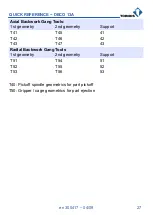
Axial Backwork Gang Tools:

1st geometry

2nd geometry

Support

T41

T45

41

T42

T46

42

T43

T47

43

Radial Backwork Gang Tools

1st geometry

2nd geometry

Support

T51

T54

51

T52

T55

52

T53

T56

53

T40: Pickoff spindle geometrics for part pickoff

T50: Gripper / cage geometrics for part ejection

Summary of Contents for DECO 13a

Page 1: ...QUICK REFERENCE DECO 13a en 300417 Printed in Switzerland Copyright 1999 2008 ...

Page 2: ... nor to anticipate every contingency TORNOS S A give no guarantee nor assume any responsibility for the exactitude and the sufficiency of the information contained in this document The contents of the instructions remain the property of TORNOS S A who reserve the right to modify complete or correct them at any time The original language of the instructions to be referred to is French The hazards o...

Page 3: ... GLOBAL PART VARIABLES 15 1 10 GLOBAL PROGRAM VARIABLES 16 1 11 M FUNCTIONS 17 1 12 T FUNCTIONS 26 1 13 KINEMATICS 28 1 14 AXIS NO 29 2 OPERATE MACHINE FUNCTIONS 30 2 1 REFERENCING 30 2 1 1 Reference All Axes 30 2 1 2 Reference Axis by Axis 31 2 2 MANUAL DATA INPUT MDI OPERATION 32 2 3 JOG AN AXIS 33 2 4 INCREMENT AN AXIS 34 2 5 AUTO MODE 35 2 6 RUN A PROGRAM AT 5 FEEDRATE FORWARD 36 2 7 EDIT TOOL...

Page 4: ...07005 S2 DRIVE X2 Y2 46 4 2 307009 S5 DRIVE X4 47 4 2 1 Arrangement of the drive belt S5 47 4 3 307010 S6 DRIVE X1 Y1 48 4 4 307011 S3 DRIVE X3 Z3 49 4 4 1 Arrangement of the drive belt S3 49 5 MISCELLANEOUS 50 5 1 BASIC STEPS ON WINDOWS 50 5 2 COPY ON SAME DISK 50 5 3 COPY ONTO ANOTHER DISK 50 5 4 CYCLE THROUGH WINDOWS ETC 50 5 5 COPY PASTE 50 5 6 BASIC TB DECO STEPS TO SET UP A PROGRAM 51 5 7 RE...

Page 5: ...e point for tool geometries 1 2 AXIS TRAVEL Axes Position min Position max Reference point Travel X1 14 mm 56 mm 56 mm 35 mm X2 14 mm 56 mm 56 mm 35 mm Y1 3 mm 155 mm 0 mm 158 mm Y2 3 mm 155 mm 0 mm 158 mm Z1 0 mm 255 mm 0 mm 255 mm X3 144 mm 230 mm 144 mm 187 mm Z3 160 mm 0 mm 0 mm 160 mm X4 310 mm 6 mm 0 mm 158 mm Y4 1 mm 299 mm 296 mm 300 mm Z4 0 mm 160 mm 160 mm 160 mm ...

Page 6: ...o 12 13 14 1 POSITION Display all axes 2 PROGRAM Output Input a program 3 OFFSET SETTING 4 SHIFT 5 CANCEL 6 INPUT Enter data 7 SYSTEM Access to data 8 MESSAGE Display messages alarms 9 GRAPH Display axis position 10 ALTER e g replace characters 11 INSERT 12 DELETE 13 HELP 14 RESET ...

Page 7: ...QUICK REFERENCE DECO 13A en 300417 04 08 7 1 4 CONTROL PANEL 6 1 2 3 4 5 F1 F2 F3 F4 F5 7 8 9 10 11 12 13 14 15 16 17 18 19 20 21 22 23 24 25 ...

Page 8: ...ation 9 Key Selector 10 Axis Feedrate Override decr 11 Axis Feedrate Override incr 12 Spindle Speed Override decr 13 Spindle Speed Override incr 14 Program BACKWARD inactive 15 Program FORWARD 16 Open Main Spindle Collet 17 Close Main Spindle Collet 18 Open Pickoff Spindle Collet 19 Close Pickoff Spindle Collet 20 CYCLE START 21 Program Stop 22 CYCLE STOP 23 Coolant ON 24 Adjust Coolant 25 Coolant...

Page 9: ...33 Threading constant lead 9 S G34 Threading increasing lead 9 S G35 Threading decreasing lead 9 S G40 Cutter compensation cancel 2 M G41 Cutter compensation left 2 M G42 Cutter compensation right 2 M G52 Cancel all zero offsets datum shifts Coordinate system begins at Machine Zero and is again valid for the axis axes concerned 1 M G53 Cancel all additional zero offsets datum shifts programmed via...

Page 10: ...r the axes concerned to cut with respect to Machine Zero 1 M G59 Restore all zero offsets datum shifts saved via last G58 for the axes concerned 1 M G68 Cancel G69 2 M G69 Calculate 360 modulo for rotary axis 2 M G70 Inch data input not for tools 2 M G71 Metric data input 2 M G81 Linear extension for cutter compensation 2 M G82 Circular extension for cutter compensation 2 M G83 Permute axes for ma...

Page 11: ...raverse unproductive 2 S G113 Loop End 1 S G130 Start of threading specification 8 S G131 End of threading specification 8 S G190 Exact stop between segments 2 M G191 Continuous contouring if angle 0 2 M G250 Cancel polygoning 4 S G251 Spindle ON specified by hundreds for polygo ning 4 M G314 Path π for G02 G03 function 2 S G350 Cancel polygoning 4 S G351 Spindle ON specified by hundreds for polyg...

Page 12: ...e identified by hundreds in polygon mode R2 Q 0 does not reverse the sense of rotation R2 Q 1 reverses the sens of rotation G900 Initialize spindles with settings specified for part G901 Initialize sequences Functions active by default for new operation Grp Function Group Nb M Modal Function remains active until replaced by another function of same group S Sequential Function remains active in pro...

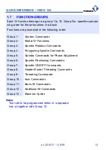
Page 13: ...odal G Functions Group 3 Spindle Rotation Commands Group 4 Polygoning Spindle Commands Group 5 Spindle Commands for Phase Adjustment Group 6 Spindle Positioning Commands Group 7 Spindle ON OFF Commands Group 8 Header Footer Threading Commands Group 9 Threading Commands Group 10 Axis Commands Group 11 Basic M Commands Group 12 Additional M Commands Group 13 Machine Cycles Note Tool call to be progr...

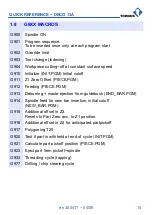
Page 14: ... PIECE PGM G912 Feeding PIECE PGM G913 Deburring waste ejection from guidebush END_BAR PGM G914 Spindle feed for new bar insertion initial cutoff NEW_BAR PGM G915 Additional offset in Z3 Resets to Part Zero acc to Z1 position G916 Additional offset in Z4 for anticipated partpickoff G917 Polygoning T25 G920 Test if part is withheld at end of cycle INIT PGM G921 Calculate part pickoff position PIECE...

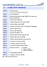
Page 15: ...deburring shift 3006 Guidebush type 0 fixed 1 rotating 2 Habegger 3007 Open collet dwell s 3008 Close collet dwell s 3009 Part pickoff length 3010 Pickoff spindle collet geometry 3011 Retract after part pickoff 3012 Pickoff spindle approach distance 3014 Z1 retract to eject waste 3015 Z1 feed to insert new bar 3016 S1 speed to feed next part rpm 3017 Ejection method 0 Gripper 1 Tray Ejector 2 Grip...

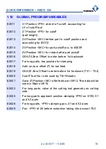
Page 16: ...4 Zero Offset to enter before 1st backwork 2017 For long parts bar position for clamping 2018 Add on zero offset Z1 for bar feed 2019 G56 Z3 Zero Offset to enter before 1st frontwork T31 T34 2020 Cutoff Tool No to be used by TB Wizards 2021 Save Z1 Position MC after feed over G912 This data will be used in Macro G915 2022 For long parts value of the cutting tool geometry on cutting side 2025 For l...

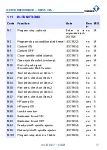
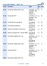
Page 17: ...ts Part Counter DO1923 no S M32 Tool break check on Sens 1 DO1942 no S M33 Part pres check on Sens 1 DO1943 no S M34 Tool break check on Sens 2 DO1944 no S M35 Part pres check on Sens 2 DO1945 no S M36 Tool break check on Sens 3 DO1946 no S M37 Part pres check on Sens 3 DO1947 no S M45 HP pump On DO1950 yes S M46 HP pump Off DO1951 yes S M60 Load a new bar DO1927 no S M82 Barfeeder thrust ON DO193...

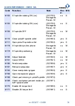
Page 18: ...02 yes S M118 S1 spindle synchro phase Disregards Param W no M M119 S1 spindle positioning Disregards Param W no M M150 Adjust feedrate DO1940 no M M151 Cancel M150 DO1941 no M M160 Feed manipulator DO1906 yes S M161 Retract manipulator DO1907 yes S M164 Close manipulator gripper DO1935 yes S M165 Open manipulator gripper DO1936 yes S M168 Check part missing in pickoff spindle DO1970 M169 Check wo...

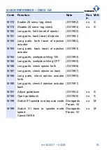
Page 19: ...k travel of ejection actuator DO1983 M184 Long parts workpiece tilting ON DO1984 M185 Long parts workpiece tilting OFF DO1985 M186 Long parts check ejector forth DO1986 M187 Long parts check ejector on back DO1987 M188 Long parts check ejector actuator forth DO1990 M189 Long parts check if ejection actuator back DO1991 M191 Adjust guidebush DO1924 no S M192 Open guidebush DO1926 no S M198 Switch S...

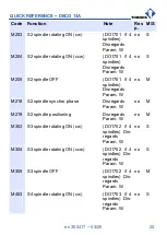
Page 20: ...DO1701 if 4 spindles Disregards Param W no M M218 S2 spindle synchro phase Disregards Param W no M M219 S2 spindle positioning Disregards Param W no M M303 S3 spindle rotating ON cw DO1702 if 4 spindles Dis regards Param W no S M304 S3 spindle rotating ON ccw DO1702 if 4 spindles Dis regards Param W no S M305 S3 spindle OFF DO1702 if 4 spindles Dis regards Param W no M M403 S4 spindle rotating ON ...

Page 21: ...isregards Param W no M M419 S4 spindle positioning Disregards Param W no M M498 Switch S4 spindle to rotary axis Disregards Param W no M M499 Reset S4 spindle ON Cancel M498 Disregards Param W no M M503 S5 spindle rotating ON cw DO1704 DO1710 DO 1724 Disregards Param W no S M504 S5 spindle rotating ON ccw DO1704 if 4 spindles Dis regards Param W no S M505 S5 spindle OFF DO1704 DO1710 DO 1724 Disre...

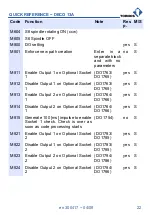
Page 22: ...ional Socket 1 DO1763 DO1765 yes S M813 Enable Output 2 on Optional Socket 1 DO1764 DO1766 yes S M814 Disable Output 2 on Optional Socket 1 DO1764 DO1766 yes S M815 Generate 100 ms impulse to enable Socket 1 check Check is over as soon as code processing starts DO 1754 no S M821 Enable Output 1 on Optional Socket 2 DO1783 DO1785 yes S M822 Disable Output 1 on Optional Socket 2 DO1783 DO1785 yes S ...

Page 23: ...04 DO1806 yes S M834 Disable Output 2 on Optional Socket 3 DO1804 DO1806 yes S M835 Generate 100 ms impulse to enable Socket 3 check Check is over as soon as code processing starts DO 1794 no S M841 Enable output 1 on optional Socket 4 DO1823 DO1825 yes S M842 Disable output 1 on optional Socket 4 DO1823 DO1825 yes S M851 Enable output 1 on optional Socket 5 DO1843 DO1845 yes S M852 Disable output...

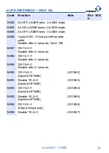
Page 24: ...Flush pickoff spindle collet Disable after 2 seconds Timer T26 M887 ON Y4 3 1 Disable after 2 seconds M888 ON Y4 1 1 Disable after 2 seconds M889 ON Y5 6 1 Disable after 2 seconds M890 ON Y5 4 1 Spindle HF NSK DO1862 M891 Disable Y5 4 0 Spindle HF NSK DO1863 M892 ON Y5 2 1 Spindle HF NSK DO1864 M893 Disable Y5 2 0 Spindle HF NSK DO1865 M894 ON Y5 0 1 deep drilling pump DO1866 M895 Disable Y5 0 0 D...

Page 25: ... table above can be accompanied by one Parameter specifying Anticipated Response Time ms of a particular item indepen dently of the override All M functions are executed DURING the block Put M function in the next block if you want it to be executed AFTER the block No block processing time is necessary for PNC DECO and all synchros are possible 1 segment 1 M function All M functions can be accompa...

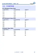
Page 26: ...metry 2nd geometry Support T11 T16 11 T12 T17 12 T13 T18 13 T14 T19 14 T15 T20 15 X2Y2 Mainwork Gang Tools 1st geometry 2nd geometry Support T21 T26 21 T22 T27 22 T23 T28 23 T24 T29 24 T25 T30 25 Frontwork Gang Tools 1st geometry 2nd geometry Support T31 T35 31 T32 T36 32 T33 T37 33 T34 T38 34 ...

Page 27: ...ng Tools 1st geometry 2nd geometry Support T41 T45 41 T42 T46 42 T43 T47 43 Radial Backwork Gang Tools 1st geometry 2nd geometry Support T51 T54 51 T52 T55 52 T53 T56 53 T40 Pickoff spindle geometrics for part pickoff T50 Gripper cage geometrics for part ejection ...

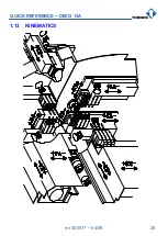
Page 28: ...QUICK REFERENCE DECO 13A en 300417 04 08 28 1 13 KINEMATICS ...

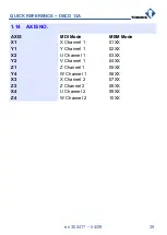
Page 29: ...8 29 1 14 AXIS NO AXIS MDI Mode MEM Mode X1 X Channel 1 01XX Y1 Y Channel 1 02XX X2 U Channel 1 03XX Y2 V Channel 1 04XX Z1 Z Channel 1 05XX Y4 W Channel 1 06XX X3 X Channel 2 07XX Z3 Z Channel 2 08XX X4 U Channel 2 09XX Z4 W Channel 2 10XX ...

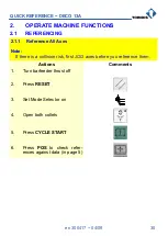
Page 30: ...NCING 2 1 1 Reference All Axes Note If there is a collision risk first JOG axes before you reference them Actions Comments 1 Turn barfeeder thrust off 2 Press RESET 3 Set Mode Selector on 4 Open both collets 5 Press CYCLE START 6 Press POS to check refer ences against data in page 5 ...

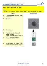
Page 31: ...collision risk first JOG axes before you reference them Actions Comments 1 Turn barfeeder thrust off to ref erence Z1 2 Select axis 3 Selector on 4 Turn barfeeder thrust off if REF Z1 Z4 Open collet regarding Z1 or Z4 5 Press CYCLE START 6 Press POS to check refer ences against data in Page 5 ...

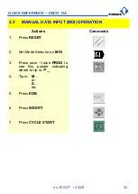
Page 32: ...08 32 2 2 MANUAL DATA INPUT MDI OPERATION Actions Comments 1 Press RESET 2 Set Mode Selector on MDI 3 Press once twice PROG to see this pointer indicating where to tip in _ 4 Tip in M or S etc 5 Press EOB 6 Press INSERT 7 Press CYCLE START ...

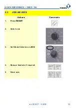
Page 33: ...QUICK REFERENCE DECO 13A en 300417 04 08 33 2 3 JOG AN AXIS Actions Comments 1 Press RESET 2 Select axis 3 Set Mode Selector on JOG 4 Reduce feedrate if required 5 Move axis ...

Page 34: ...QUICK REFERENCE DECO 13A en 300417 04 08 34 2 4 INCREMENT AN AXIS Actions Comments 1 Press RESET 2 Select axis 3 Select increment Note X1 0 0001 mm 4 Move axis ...

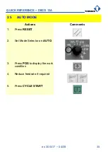
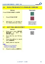
Page 35: ...CK REFERENCE DECO 13A en 300417 04 08 35 2 5 AUTO MODE Actions Comments 1 Press RESET 2 Set Mode Selector on AUTO 3 Press POS to display the work condition 4 Reduce feedrate if required 5 Press CYCLE START ...

Page 36: ...E STOP 2 Hold down to advance at 5 Release the key to stop 2 7 EDIT TOOL WEAR OFFSET Actions Comments 1 Press once twice OFFSET SETTING to open the OFFSET page 2 Tip in Axis No over NC key board 3 Press this softkey to search axis AXISRH 4 Modify offset as required Note Editing in μm microns Editing X at Diameter 5 Press this softkey INPUT ...

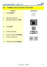
Page 37: ...7 04 08 37 2 8 DISABLE X3 Z3 S3 X4 Y4 Z4 AXIS Actions Comments 1 Press RESET 2 Reference machine 3 Set Mode Selector on MDI 4 Press POS 5 Press this softkey 6 Press this softkey STATAX 7 Press to select axis 8 Press this softkey INACTI ...

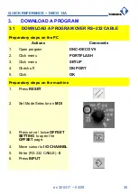
Page 38: ...on the PC Actions Comments 1 Open program DNC DECO V5 2 Click menu PORT FLASH 3 Click menu SETUP 4 Check off ON PORT 5 Click OK Preparatory steps on the machine 1 Press RESET 2 Set Mode Selector on MDI 3 Press once twice OFFSET SETTING to open the OFFSET page 4 Move cursor to I O CHANNEL 5 Enter RS 232 CABLE 0 6 Press INPUT ...

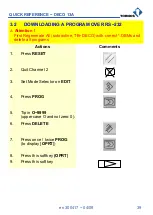
Page 39: ...erate All subroutine TB DECO with correct DBMs and delete all programs Actions Comments 1 Press RESET 2 Quit Channel 2 2 3 Set Mode Selector on EDIT 4 Press PROG 5 Tip in O 9999 upper case O and not zero 0 6 Press DELETE 7 Press once twice PROG to display OPRT 8 Press this softkey OPRT 9 Press this softkey ...

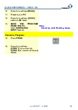
Page 40: ...11 Prepare your PC 12 Press this softkey EXEC Letters LSK flash 13 SEND THE PROGRAM FROM THE PC Click DOWNLOAD INPUT flashes Note Stand by until flashing stops Convert a Program 14 Press PROG 15 Press this softkey CONV 1 to convert all CONV 3 to convert all except offsets ...

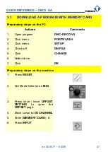
Page 41: ...s 1 Open program DNC DECO V5 2 Click menu PORT FLASH 3 Click menu SETUP 4 Check off ON FILE 5 Click CHANGE 6 Select drive 7 Click OK Preparatory steps on the machine 1 Press RESET 2 Set Mode Selector on MDI 3 Press once twice OFFSET SETTING to open the OFFSET page 4 Move cursor to I O CHANNEL 5 Enter MEMORY CARD 4 6 Press INPUT ...

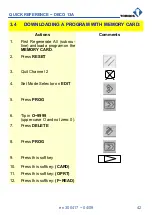
Page 42: ...Regenerate All subrou tine and load a program on the MEMORY CARD 2 Press RESET 3 Quit Channel 2 2 4 Set Mode Selector on EDIT 5 Press PROG 6 Tip in O 9999 upper case O and not zero 0 7 Press DELETE 8 Press PROG 9 Press this softkey 10 Press this softkey CARD 11 Press this softkey OPRT 12 Press this softkey F READ ...

Page 43: ...13 Select Program No 14 Press this softkey F SET 15 Press this softkey EXEC INPUT flashes Note Stand by until flashing stops Das Programm konvertieren 16 Press PROG 17 Press this softkey CONV 1 to convert all CONV 3 to convert all except offsets ...

Page 44: ... tool With this function you can retrieve OFFSETS of the other tools Actions Contents After loading the tables 1 Press this softkey CONV 1 2 Press once twice OFFSET SETTING to open the OFFSET page 3 Press this softkey 4 Press this softkey RESTO Δ Attention After a CONV 1 no value must be entered in OFFSET pages before RESTOring offsets ...

Page 45: ...QUICK REFERENCE DECO 13A en 300417 04 08 45 4 DRIVE ...

Page 46: ...QUICK REFERENCE DECO 13A en 300417 04 08 46 4 1 307005 S2 DRIVE X2 Y2 307005f3 ...

Page 47: ...QUICK REFERENCE DECO 13A en 300417 04 08 47 4 2 307009 S5 DRIVE X4 4 2 1 Arrangement of the drive belt S5 307009f2 ...

Page 48: ...QUICK REFERENCE DECO 13A en 300417 04 08 48 4 3 307010 S6 DRIVE X1 Y1 307010f3 ...

Page 49: ...QUICK REFERENCE DECO 13A en 300417 04 08 49 4 4 307011 S3 DRIVE X3 Z3 4 4 1 Arrangement of the drive belt S3 307009f2 ...

Page 50: ...light drag Ctrl drop to copy files 5 3 COPY ONTO ANOTHER DISK Highlight drag drop to copy files Highlight drag Ctrl drop to move files 5 4 CYCLE THROUGH WINDOWS ETC Ctrl Tab Cycles through active TB DECO windows Alt Tab Cycles through interacitve applications 5 5 COPY PASTE Ctrl C Copies a highlighted item Closes active application Opens target application Ctrl V Pastes the highlighted item in the...

Page 51: ...17 04 08 51 5 6 BASIC TB DECO STEPS TO SET UP A PROGRAM Start up TB DECO Generate a new part Edit Tool Catalogue Enter spindle speeds Enter Global Variables Edit operations Impose Synchros Constraints Generate tables Make a simulation ...

Page 52: ...QUICK REFERENCE DECO 13A en 300417 04 08 52 5 7 REFILLING CHUCKING HYDRAULICS OK KO Y360 1 2 3 4a 4b 5 6 0 ...

Page 53: ...ments Open Program Edit_BD V5 1 Click Startup 2 Select Programs 3 Select DECO 2000 V5 4 Click Edit_BD V5 Open machine data base from Window Edit bd 1 Click File 2 Click Open 3 Select database Machine No 4 Click Open 5 Double click Support 6 Click Support 31 7 Double click axis to modify e g Offset X 8 Enter value in setting box 9 Click OK File Save File Exit ...

Reviews: