Hydraulic
System
Reelmaster 5500-D
Hydraulic System (Rev. C)
Page 4 - 75
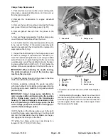
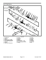
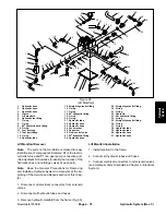
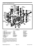
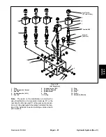
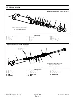
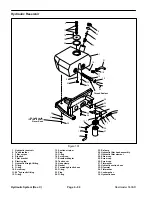
Adjusting Valve (Cross-over Relief Valve) Service
Note: The adjusting valve (#8 Fig. 87) must be re-
placed as a complete assembly. Disassemble parts for
cleaning and inspection only.
1. Disassemble the adjusting valve parts. DO NOT at-
tempt to remove the valve seat. It is installed with thread
locking compound at the factory.
2. Inspect adjusting valve bore and seat in valve block.
3. Inspect spring for damage.
4. Clean and air dry all parts. Apply hydraulic oil to parts
and install in the same order they were removed.
Disassembly
Note: Parts must be replaced as a kit. Gears, gear
housing and bearing blocks cannot be serviced sepa-
rately. Replace complete motor if these parts are dam-
aged or severely worn. Refer to your Parts Catalog for
more information on available reel motor kits.
IMPORTANT: The motor is “run-in” at the factory to
obtain precise parts tolerances. Keep housing,
gears and bearings for each motor together. DO
NOT mix parts between different motors.
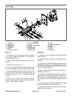
1. Plug ports and wash exterior of motor with cleaning
solvent.
2. Draw a line across seam areas on flange, gear hous-
ing and valve block with a scribe or marker to ensure
proper reassembly.
IMPORTANT: Use caution when clamping in a vise
to avoid distorting any parts.
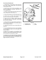
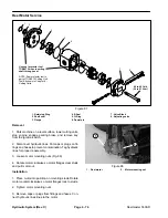
3. Secure the flange end of the motor in a vise with the
drive shaft pointing down (Fig. 87).
4. Remove the four capscrews.
5. Put your hand on the case and gently tap case with
a soft face hammer to loosen the sections. Be careful not
to drop parts or disengage gear mesh.
6. Remove valve block (Fig. 87).
7. Remove gear housing. Make sure rear bearing block
remains on drive and idler gear shafts.
8. Remove rear bearing block from drive and idler gear
shafts.
9. Before removing gear set, apply marking dye to mat-
ing teeth to retain “timing”. Motor efficiency may be af-
fected if the teeth are not installed in the same position
during reassembly.
10.Remove idler gear.
11. Remove drive gear and shaft slowly until drive end
is through shaft seal.
12.Remove front bearing block.
13.Wash all parts in cleaning solvent. Check all parts for
burrs, scoring, nicks and other damage. If gears, hous-
ing or bearing blocks are damaged or severely worn, en-
tire motor should be replaced.
Seal Replacement (Motor Disassembled)
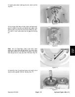
1. Put flange on a clean, flat surface with shaft seal fac-
ing up. Remove retaining ring (Fig. 87).
2. Remove shaft seal, being careful not to scratch seal
bore in flange. Scratches in seal bore could cause leak-
age. Make sure seal bore is clean.
3. Put new shaft seal (part number side up) in seal bore
and press seal into bore until seal reaches bottom of
bore. Uniform pressure must be applied to face of shaft
seal to prevent damage to seal and misalignment in seal
bore.
4. Install retaining ring with sharp edge facing out.
E-seal Replacement
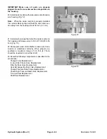
1. Put bearing block on a clean, flat surface with E-seal
facing up (Fig. 87). Remove E-seal. Clean E-seal
groove.
2. Apply a light coating of grease or petroleum jelly in
E-seal groove and on back (flat) side of new E-seal. Put
E-seal, flat side up, into groove in bearing block.
3. Repeat for other bearing block.
O-ring Replacement
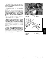
1. Remove dowel pins and O-rings from gear housing.
Clean O-ring grooves (Fig. 87).
2. Apply a light coating of grease or petroleum jelly to
O-ring grooves in gear housing and install new O-rings
in each groove.
Summary of Contents for 00075SL
Page 2: ...Reelmaster 5500 D ...
Page 4: ...Reelmaster 5500 D ...
Page 6: ...Reelmaster 5500 D ...
Page 64: ...Reelmaster 5500 D Hydraulic System Rev C Page 4 26 This page is intentionally blank ...
Page 170: ...Reelmaster 5500 D Page 5 40 Electrical System Rev C ...
Page 192: ...Reelmaster 5500 D Differential Axle Page 6 22 ...
Page 254: ...Reelmaster 5500 D Groomer Rev C Page 8 1 14 ...
Page 278: ...Reelmaster 5500 D Page 10 2 Electrical Diagrams Rev C ...
Page 284: ...Rev C Page 10 8 Harness Drawing Reelmaster 5500 D Serial Number 210000401 to 210999999 ...
Page 285: ...Rev C Page 10 9 Harness Diagram Reelmaster 5500 D Serial Number 210000401 to 210999999 ...
Page 286: ...Rev C Page 10 10 Harness Drawing Reelmaster 5500 D Serial Number 220000001 to 220999999 ...
Page 287: ...Rev C Page 10 11 Harness Diagram Reelmaster 5500 D Serial Number 220000001 to 220999999 ...
Page 288: ...Rev C Page 10 12 Harness Drawing Reelmaster 5500 D Serial Number Above 230000000 ...
Page 289: ...Rev C Page 10 13 Harness Diagram Reelmaster 5500 D Serial Number Above 230000000 ...
Page 290: ...Reelmaster 5500 D ...

