Electrical
System
Reelmaster 5500-D
Page 5 - 5
Electrical System (Rev. C)
Troubleshooting
CAUTION
Remove all jewelry, especially rings and
watches, before doing any electrical trouble-
shooting or testing. Disconnect the battery
cables unless the test requires battery voltage.
For effective troubleshooting and repairs, you must
have a good understanding of the electrical circuits and
components used on this machine (see Electrical Sche-
matics and Electrical Harness and Connectors Drawing
section of this chapter).
If the machine has any interlock switches by-passed,
they must be reconnected for proper troubleshooting
and safety.
Quick Reference Troubleshooting Guide
Diagnostic Light
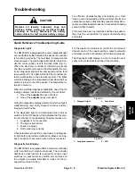
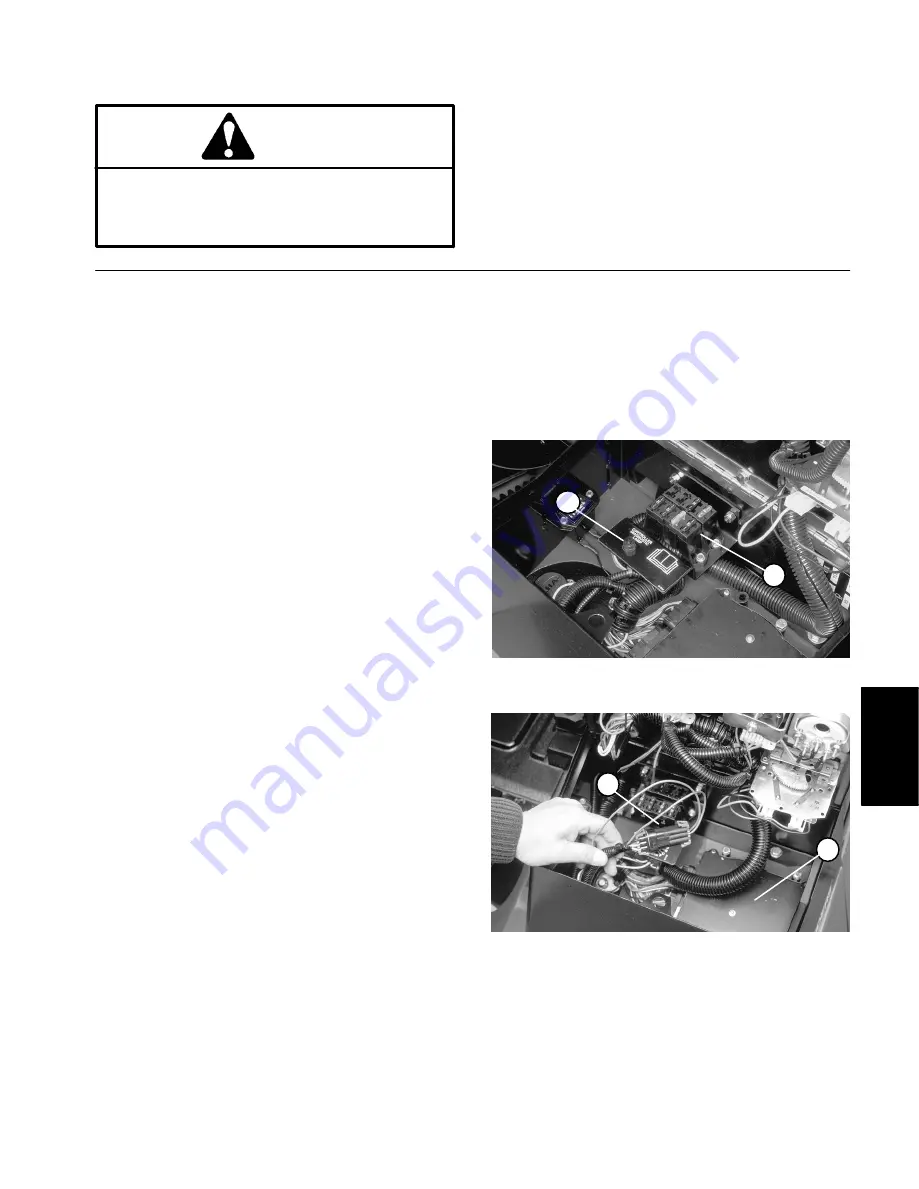
The RM 5500-D is equipped with a green diagnostic light
and red fault lamp that indicate if the electronic controller
is functioning correctly. The fault lamp is located on the
steering tower. The green diagnostic light is located un-
der the control panel, next to the fuse block (Fig. 5).
When the electronic controller is functioning correctly
and the key switch is moved to the ON position, the con-
troller diagnostic light will be illuminated and the fault
lamp will be off. The lights will blink if the controller de-
tects a malfunction in the electrical system. The lights
will stop blinking and automatically reset when the key
switch is turned to the OFF position. The fault will be re-
tained in memory.
When the controller diagnostic light blinks, one of the fol-
lowing problems has been detected by the controller:
1. One of the outputs has been shorted.
2. One of the outputs is open circuited.
Using the diagnostic display, determine which output is
malfunctioning (see Verify Output Functions and Re-
trieving Stored Faults).
If the diagnostic light is not illuminated when the key
switch is in the ON position, this indicates that the elec-
tronic controller is not operating. Possible causes are:
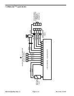
1. Loopback is not connected.
2. The light is burned out.
3. Fuses are blown.
4. Not functioning correctly.
Check electrical connections, input fuses, and diagnos-
tic light bulb to determine malfunction. Make sure loop-
back connector is secured to wire harness connector.
Diagnostic Ace Display
The RM 5500-D is equipped with an electronic controller
which controls most machine functions. The controller
determines what function is required for various input
switches (i.e. seat sensor, key switch, etc.) and turns on
the outputs to actuate solenoids or relays for the re-
quested machine function.
For the electronic controller to control the machine as
desired, each of the input switches, output solenoids
and relays must be connected and functioning properly.
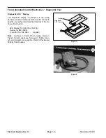
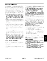
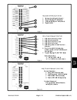
The Diagnostic ACE display is a tool to help the user
verify correct electrical functions of the machine.
1. Diagnostic
light
2. Fuse
block
Figure 5
1
2
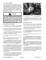
1. Loopback
connector
2. ECU
Figure 6
1
2
Summary of Contents for 00075SL
Page 2: ...Reelmaster 5500 D ...
Page 4: ...Reelmaster 5500 D ...
Page 6: ...Reelmaster 5500 D ...
Page 64: ...Reelmaster 5500 D Hydraulic System Rev C Page 4 26 This page is intentionally blank ...
Page 170: ...Reelmaster 5500 D Page 5 40 Electrical System Rev C ...
Page 192: ...Reelmaster 5500 D Differential Axle Page 6 22 ...
Page 254: ...Reelmaster 5500 D Groomer Rev C Page 8 1 14 ...
Page 278: ...Reelmaster 5500 D Page 10 2 Electrical Diagrams Rev C ...
Page 284: ...Rev C Page 10 8 Harness Drawing Reelmaster 5500 D Serial Number 210000401 to 210999999 ...
Page 285: ...Rev C Page 10 9 Harness Diagram Reelmaster 5500 D Serial Number 210000401 to 210999999 ...
Page 286: ...Rev C Page 10 10 Harness Drawing Reelmaster 5500 D Serial Number 220000001 to 220999999 ...
Page 287: ...Rev C Page 10 11 Harness Diagram Reelmaster 5500 D Serial Number 220000001 to 220999999 ...
Page 288: ...Rev C Page 10 12 Harness Drawing Reelmaster 5500 D Serial Number Above 230000000 ...
Page 289: ...Rev C Page 10 13 Harness Diagram Reelmaster 5500 D Serial Number Above 230000000 ...
Page 290: ...Reelmaster 5500 D ...

