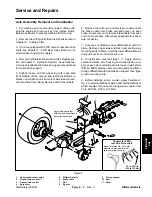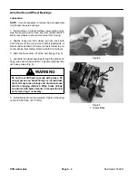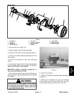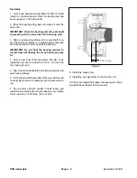
Reelmaster 5500-D
Page 5 - 32
Electrical System (Rev. C)
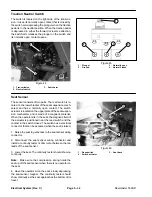
Traction Neutral Switch
The switch is located on the right side of the transmis-
sion. It uses its normally open contact that is closed by
the switch arm depressing the plunger when the traction
pedal is in the neutral position. When the traction pedal
is depressed in either the forward or reverse direction,
the switch arm releases the plunger on the switch and
its normally open contact opens.
1. Transmission
2. Neutral
switch
3. Switch
arm
Figure 44
2
1
1. Plunger
2. Ground
3. Normally
open
4. Normal
closed
Figure 45
4
2
3
1
Seat Sensor
The sensor consists of two parts. The reed switch is lo-
cated on the lower bracket of the seat suspension mech-
anism and has a normally open contact. The switch
actuator is located on the upper plate of the seat suspen-
sion mechanism and is made of a magnetic material.
When the operator sits in the seat, the magnetic field of
the actuator is positioned near the reed switch and the
contact in the switch closes. The switch has a electrical
connector that can be accessed when the seat is raised.
1. Raise the seat to get access to the seat sensor wiring
connector.
2. Disconnect the seat sensor wiring connector and
install a continuity tester or ohm meter between the two
leads of the seat sensor.
3. Lower the seat. The continuity tester should show no
continuity.
Note: Make sure the compression spring holds the
seat up off the seat sensor when there is no operator on
the seat.
4. Have the operator sit on the seat, slowly depressing
the seat sensor magnet. The continuity tester should
show continuity as the seat approaches the bottom of its
travel.
1. Reed
switch
2. Switch
actuator
3. Seat
back
Figure 46
2
1
3
Summary of Contents for 00075SL
Page 2: ...Reelmaster 5500 D ...
Page 4: ...Reelmaster 5500 D ...
Page 6: ...Reelmaster 5500 D ...
Page 64: ...Reelmaster 5500 D Hydraulic System Rev C Page 4 26 This page is intentionally blank ...
Page 170: ...Reelmaster 5500 D Page 5 40 Electrical System Rev C ...
Page 192: ...Reelmaster 5500 D Differential Axle Page 6 22 ...
Page 254: ...Reelmaster 5500 D Groomer Rev C Page 8 1 14 ...
Page 278: ...Reelmaster 5500 D Page 10 2 Electrical Diagrams Rev C ...
Page 284: ...Rev C Page 10 8 Harness Drawing Reelmaster 5500 D Serial Number 210000401 to 210999999 ...
Page 285: ...Rev C Page 10 9 Harness Diagram Reelmaster 5500 D Serial Number 210000401 to 210999999 ...
Page 286: ...Rev C Page 10 10 Harness Drawing Reelmaster 5500 D Serial Number 220000001 to 220999999 ...
Page 287: ...Rev C Page 10 11 Harness Diagram Reelmaster 5500 D Serial Number 220000001 to 220999999 ...
Page 288: ...Rev C Page 10 12 Harness Drawing Reelmaster 5500 D Serial Number Above 230000000 ...
Page 289: ...Rev C Page 10 13 Harness Diagram Reelmaster 5500 D Serial Number Above 230000000 ...
Page 290: ...Reelmaster 5500 D ...

