Cutting Units
Reelmaster 5500-D
Page 8 - 11
Cutting Units
Note:
The second screw setting will change through-
out the life of the bedknife and reel due to wear, even if
the height-of-cut is not changed. Therefore, after ini-
tial set up use Checking and Adjusting Attitude for
Used Cutting Unit procedure.
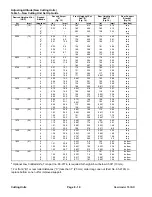
Table 1 lists starting dimensions for setting up a new cut-
ting unit with attitudes of 2, 4, 6 and 8 degrees.
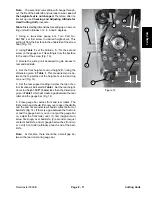
1. Using a two-screw gauge bar, Toro Part No.
98-1852, set first screw to desired height-of-cut. This
setting is from the bar face to the underside of the screw
head (Fig. 13).
2. Using Table 1, set the attitude, “A,” for the second
screw on the gauge bar. This setting is from the bar face
to the end of the screw (Fig. 13).
3. Rotate the cutting unit backward to gain access to
reel and bedknife.
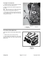
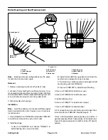
4. Set the front height-of-cut rod height,“B,” using the
dimension given in Table 1. This measurement is be-
tween the top surface of the height-of-cut rod and top
cone nut (Fig. 14).
5. Set the rear support casting in either the top or bot-
tom location as indicated in Table 1. Set the rear height-
of-cut rod height .100” (3 mm) less than the dimension
given in Table 1 which will create a gap between the rear
roller and the gauge bar (Fig. 14).
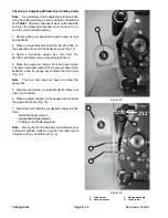
6. Place gauge bar across front and rear rollers. The
first screw head should fit snugly over edge of bedknife
and the end of second screw should contact bottom of
bedknife (Fig. 14). If there is a gap between the front roll-
er and the gauge bar or you can not put the gauge bar
on, adjust the front roller until: (1) first (height-of-cut)
screw fits snugly over bedknife, (2) second screw just
contacts bedknife, and (3) gauge bar touches front roll-
er. Verify front roller (attitude) at each end of the bed-
knife.
Note:
At this time, there should be a small gap be-
tween the rear roller and gauge bar.
3
Figure 14
“B”
“C”
1
2
3
4
4
Summary of Contents for 00075SL
Page 2: ...Reelmaster 5500 D ...
Page 4: ...Reelmaster 5500 D ...
Page 6: ...Reelmaster 5500 D ...
Page 64: ...Reelmaster 5500 D Hydraulic System Rev C Page 4 26 This page is intentionally blank ...
Page 170: ...Reelmaster 5500 D Page 5 40 Electrical System Rev C ...
Page 192: ...Reelmaster 5500 D Differential Axle Page 6 22 ...
Page 254: ...Reelmaster 5500 D Groomer Rev C Page 8 1 14 ...
Page 278: ...Reelmaster 5500 D Page 10 2 Electrical Diagrams Rev C ...
Page 284: ...Rev C Page 10 8 Harness Drawing Reelmaster 5500 D Serial Number 210000401 to 210999999 ...
Page 285: ...Rev C Page 10 9 Harness Diagram Reelmaster 5500 D Serial Number 210000401 to 210999999 ...
Page 286: ...Rev C Page 10 10 Harness Drawing Reelmaster 5500 D Serial Number 220000001 to 220999999 ...
Page 287: ...Rev C Page 10 11 Harness Diagram Reelmaster 5500 D Serial Number 220000001 to 220999999 ...
Page 288: ...Rev C Page 10 12 Harness Drawing Reelmaster 5500 D Serial Number Above 230000000 ...
Page 289: ...Rev C Page 10 13 Harness Diagram Reelmaster 5500 D Serial Number Above 230000000 ...
Page 290: ...Reelmaster 5500 D ...

