Cutting Units
Reelmaster 5500-D
Page 8 - 15
Cutting Units
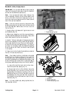
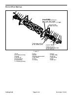
Rear Shield Adjustment
Under most conditions, best dispersion is attained when
rear shield is closed (front discharge). When conditions
are heavy or wet, rear shield may be opened.
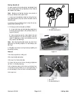
1. To open rear shield, loosen flange head capscrews
securing shield to right side plate, rotate shield to open
position and tighten screw.
Lift Chain Adjustment
The chain connecting carrier frame to cutting unit con-
trols the amount of fore-aft rotation available, as well as
the amount of ground clearance in transport and turn
around. The chain has a total of 13 links. The chain is
factory adjusted at the eleventh link, which will work well
for most fairways.
On rougher ground, chain may be shortened to allow for
more ground clearance. To allow greater rotation for
areas with many contours, lengthen chain.
Note:
The position of the screw within the link will af-
fect the chain length.
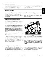
Adjusting Turf Compensation Spring
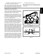
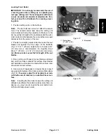
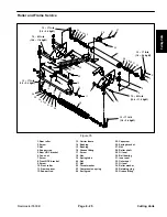
The Turf Compensation Spring (Fig. 21), connecting
carrier frame to cutting unit, controls the amount of fore-
aft rotation available, as well as the amount of ground
clearance in transport and turn around.
The Turf Compensation Spring also transfers weight
from the front to rear roller. This helps to reduce a wave
pattern in the turf, also known as bobbing.
IMPORTANT: Make spring adjustments with cutting
unit mounted to traction unit and lowered to shop floor.
Refer to Traction Unit Operator’s Manual for mounting
instructions.
1. Tighten lock nut on rear of spring rod until the gap (C)
between rear of spring bracket and front of washer is 1”
(26 mm) (Fig. 21).
2. Tighten hex nuts on front end of spring rod until the
compressed length (A) of spring is 8” (203 mm) (Fig. 21).
Note:
When cutting rough or undulating turf, increase
compressed length (A) of spring to 8-1/2” (216 mm) and
gap (C) between rear of spring bracket and front of
washer to 1-1/2” (39 mm) (Fig. 21).
Figure 21
“C”
“A”
“B”
Note:
As compressed spring length (A) decreases,
weight transfer from front roller to rear roller increases
and carrier frame/cutting unit rotation angle (B) de-
creases.
Note:
As gap (C) between spring bracket and washer
increases, cutting unit ground clearance decreases
and carrier frame/cutting unit rotation angle (B) in-
creases.
Adjusting Front Cutting Unit Travel
Additional downward travel of the front three cutting
units may be desirable in highly contoured locations. If
any of the front three cutting units lift off the ground when
cresting a “hill”, the front carrier frame may be lowered
by removing mounting bolts and repositioning frame in
the bottom set of holes in the main frame.
Summary of Contents for 00075SL
Page 2: ...Reelmaster 5500 D ...
Page 4: ...Reelmaster 5500 D ...
Page 6: ...Reelmaster 5500 D ...
Page 64: ...Reelmaster 5500 D Hydraulic System Rev C Page 4 26 This page is intentionally blank ...
Page 170: ...Reelmaster 5500 D Page 5 40 Electrical System Rev C ...
Page 192: ...Reelmaster 5500 D Differential Axle Page 6 22 ...
Page 254: ...Reelmaster 5500 D Groomer Rev C Page 8 1 14 ...
Page 278: ...Reelmaster 5500 D Page 10 2 Electrical Diagrams Rev C ...
Page 284: ...Rev C Page 10 8 Harness Drawing Reelmaster 5500 D Serial Number 210000401 to 210999999 ...
Page 285: ...Rev C Page 10 9 Harness Diagram Reelmaster 5500 D Serial Number 210000401 to 210999999 ...
Page 286: ...Rev C Page 10 10 Harness Drawing Reelmaster 5500 D Serial Number 220000001 to 220999999 ...
Page 287: ...Rev C Page 10 11 Harness Diagram Reelmaster 5500 D Serial Number 220000001 to 220999999 ...
Page 288: ...Rev C Page 10 12 Harness Drawing Reelmaster 5500 D Serial Number Above 230000000 ...
Page 289: ...Rev C Page 10 13 Harness Diagram Reelmaster 5500 D Serial Number Above 230000000 ...
Page 290: ...Reelmaster 5500 D ...

