Reelmaster 5500-D
Hydraulic System (Rev. C)
Page 4 - 30
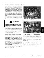
TEST NO. 3: Relief Valve (R1) and (R2) Pressure
Note:
The front mowing circuit is protected by relief
valve (R1). The rear mowing circuit is protected by relief
valve (R2). See Hydraulic Flow Diagrams at the begin-
ning of this chapter.
1. Make sure hydraulic oil is at normal operating tem-
perature by operating the machine for approximately 10
minutes.
2. Make sure machine is parked on a level surface with
the cutting units lowered and off. Make sure engine is off
and the parking brake is engaged.
CAUTION
Prevent personal injury and/or damage to equip-
ment. Read all WARNINGS, CAUTIONS, and Pre-
cautions for Hydraulic Testing at the beginning
of this section.
3. Set reel speed controls (FC1 and FC2) to full open
(highest number). Make sure backlap switch is OFF.
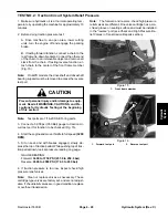
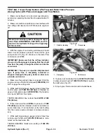
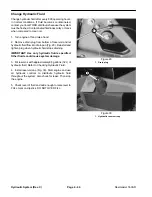
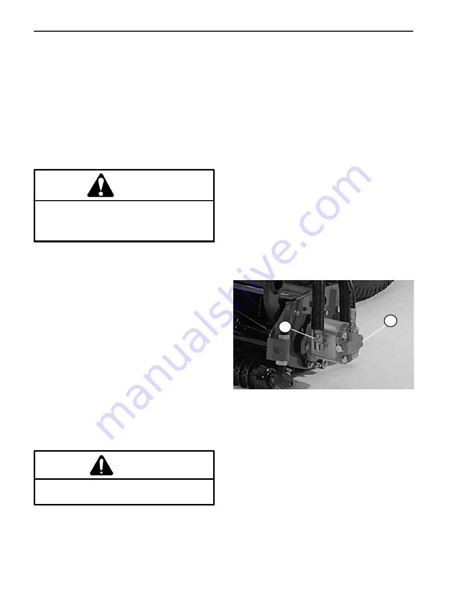
4. Disconnect pressure hose from front hydraulic fitting
on reel motor (Fig. 17):
Left front cutting unit (No. 4) for relief valve (R1)
Left rear cutting unit (No. 2) for relief valve (R2)
IMPORTANT: Make sure that the oil flow indicator
arrow on the flow meter is showing that the oil will
flow from the pump, through the tester and into the
reel motor.
5. Install tester with pressure gauges and flow meter in
series with the hose and hydraulic fitting on reel motor.
Make sure the flow control valve on tester is fully
open.
6. Start engine and move throttle to full speed (3200
RPM).
WARNING
Keep away from reels during test to prevent per-
sonal injury from rotating reel blades.
7. Have another person occupy seat, move ”Enable/
Disable” switch to ENABLE. Move ”Lower− Mow/Raise”
lever forward to engage cutting units, then monitor the
tester pressure gauge.
8. Watch pressure gauge carefully while slowly closing
the tester flow control valve to fully closed.
9. As the relief valve lifts, system pressure should be:
From 2950 to 3050 PSI (203.4 to 210.3 bar) for re-
lief valve (R1)
From 1950 to 2050 PSI (134.5 to 141.4 bar) for re-
lief valve (R2)
10.Open the tester flow control valve, disengage cutting
units and stop the engine.
11. If pressure is too high, remove cap on appropriate re-
lief valve (R1 or R2) and adjust screw to get correct pres-
sure (see Adjust Manifold Relief Valves). If pressure is
too low, check for restriction in pump intake line. If intake
line is not restricted, remove cap from appropriate relief
valve and adjust screw to get correct pressure. If pres-
sure is still too low, pump or motor should be suspected
of wear, damage or inefficiency.
12.Disconnect tester from reel motor fitting and hose.
Reconnect hydraulic hose to reel motor fitting.
2
1
1. Cutting reel motor
2. Pressure hose (front)
Figure 17
Summary of Contents for 00075SL
Page 2: ...Reelmaster 5500 D ...
Page 4: ...Reelmaster 5500 D ...
Page 6: ...Reelmaster 5500 D ...
Page 64: ...Reelmaster 5500 D Hydraulic System Rev C Page 4 26 This page is intentionally blank ...
Page 170: ...Reelmaster 5500 D Page 5 40 Electrical System Rev C ...
Page 192: ...Reelmaster 5500 D Differential Axle Page 6 22 ...
Page 254: ...Reelmaster 5500 D Groomer Rev C Page 8 1 14 ...
Page 278: ...Reelmaster 5500 D Page 10 2 Electrical Diagrams Rev C ...
Page 284: ...Rev C Page 10 8 Harness Drawing Reelmaster 5500 D Serial Number 210000401 to 210999999 ...
Page 285: ...Rev C Page 10 9 Harness Diagram Reelmaster 5500 D Serial Number 210000401 to 210999999 ...
Page 286: ...Rev C Page 10 10 Harness Drawing Reelmaster 5500 D Serial Number 220000001 to 220999999 ...
Page 287: ...Rev C Page 10 11 Harness Diagram Reelmaster 5500 D Serial Number 220000001 to 220999999 ...
Page 288: ...Rev C Page 10 12 Harness Drawing Reelmaster 5500 D Serial Number Above 230000000 ...
Page 289: ...Rev C Page 10 13 Harness Diagram Reelmaster 5500 D Serial Number Above 230000000 ...
Page 290: ...Reelmaster 5500 D ...

