paper being cut or a slight drag when the paper
is pulled.
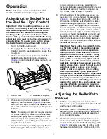
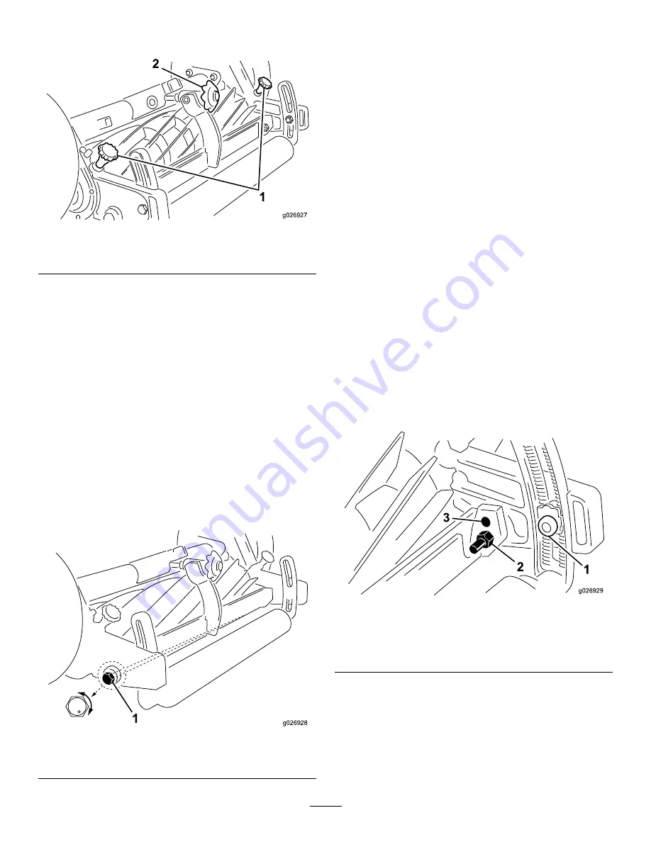
g026927
Figure 5
1.
Throwout knobs
2.
Bedknife adjusting knob
4.
Continue to check for light contact across the full
length of bedknife using paper. If light contact is
not evident, the bedknife is not parallel to the
reel.
5.
Loosen the nut on the left bedbar pivot bolt
enough to ease turning of eccentric bolt.
6.
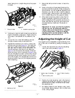
Parallel the bedknife to the reel by rotating the
left bed–bar pivot bolt (
). The left pivot
bolt has an offset thread which, when rotated,
acts as a cam to raise or lower the bedbar. On
the left hand pivot bolt there is an offset dot
(
) which denotes the thread of the bolt.
When the dot is in the up position (
) the
left end of bedbar is raised. As the bolt is turned
clockwise and the dot is lowered, so is the left
end of the bedbar. The identification dot is to be
positioned within the rear (180 degree) position
when adjusting.
g026928
Figure 6
1.
Bedbar pivot bolt
7.
Rotate the left pivot bolt to raise or lower the
bedbar.
8.
Insert a long strip of newspaper between the
reel blade and the bedknife. While rotating the
reel backward, turn the bedknife adjusting knob
clockwise, one click at a time, until the paper is
pinched lightly, which results in the paper being
cut or a slight drag when the paper is pulled.
9.
When light contact is evident across the full
length of bedknife, tighten the pivot bolt nut,
while holding the bolt in position and check to
make sure that the pivot bolt did not become
misadjusted when tightened. Readjust as
required.
Important:
To make sure that the bedknife
and the reel are not damaged while the
cutting units are transported to or installed
on the towing frame, rotate the bedknife
adjusting knob counterclockwise until the
bedknife does not touch the reel.
Adjusting the Height of Cut
The height of cut is adjustable in approximately 2.38
mm (3/32 inch) increments by raising or lowering rear
roller.
1.
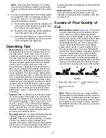
Loosen the capscrews securing the adjusting
nuts in the roller brackets (
g026929
Figure 7
1.
Bottom edge of adjusting
nut
3.
5 and 7 blade mounting
hole
2.
11 blade mounting hole
2.
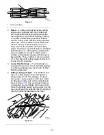
Position the roller adjusting nuts in the desired
notches and tighten the capscrews. Make sure
that the same number of notches show below
the adjusting nuts.
3.
If a higher height of cut is desired, every notch
moved adds approximately 2.38 mm (3/32 inch)
to the cutting height.
7


