Servicing the HD Dual Point
Adjusters (DPA)
1.
Remove all parts (refer to
Installation Instructions
for HD
DPA Kit Model No. 120–7230 and to Figure 33).
2.
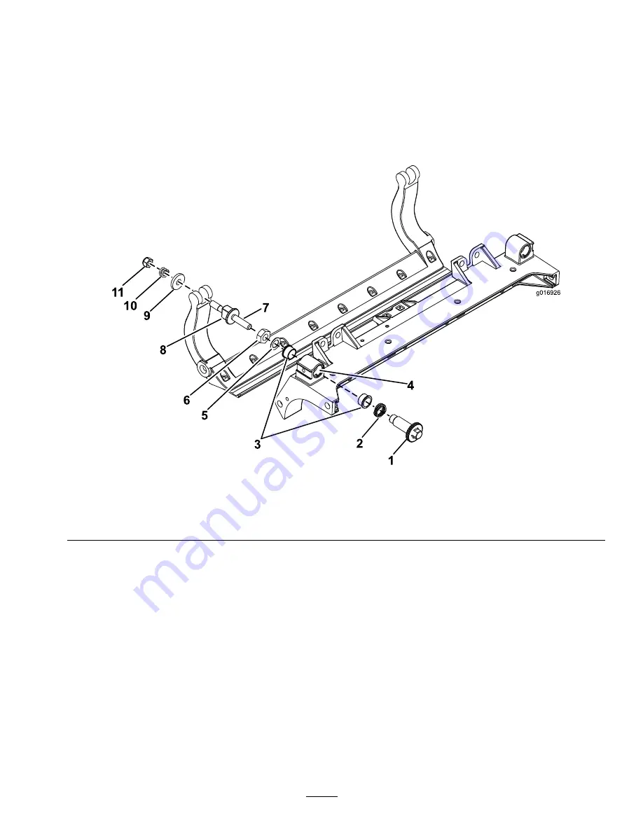
Apply Never Seize to the inside of the bushing area on
cutting unit center frame (Figure 33).
3.
Align the keys on flange bushings to the slots in the
frame and install the bushings (Figure 33).
4.
Install a wave washer onto the adjuster shaft and slide
the adjuster shaft into the flange bushings in the cutting
unit frame (Figure 33).
5.
Secure the adjuster shaft with a flat washer and lock
nut (Figure 33). Torque the lock nut to 20 to 27 N-m
(15 to 20 ft-lb).
Note:
The bedbar adjuster shaft has left-hand threads.
1
2
3
4
5
6
7
8
9
10
11
g016926
Figure 33
1.
Shaft adjuster
4.
Apply Never Seize here
7.
Apply Never Seize here
10.
Compression spring
2.
Wave washer
5.
Flat washer
8.
Bedbar adjuster screw
11.
Spring tension nut
3.
Flange bushing
6.
Lock nut
9.
Hardened washer
6.
Apply Never Seize lubricant to the threads of the
bedbar adjuster screw that fit into the adjuster shaft.
Thread bedbar adjuster screw into the adjuster shaft.
7.
Loosely install the hardened washer, spring and spring
tension nut onto adjuster screw.
8.
Install the bedbar, positioning the mounting ears
between washer and bedbar adjuster.
9.
Secure the bedbar to each side plate with the bedbar
bolts (nuts on bolts) and 6 washers. A nylon washer is
to be positioned on each side of side plate boss. Place a
steel washer outside each of the nylon washers (Figure
33). Torque bedbar bolts to 27-36 N-m (240–320
in-lb). Tighten locknuts until the outside steel washer
stops rotating and end play is removed but do not
overtighten or deflect side plates. Washers on inside
may have a gap (Figure 31).
10.
Tighten the nut on each bedbar adjuster assembly
until the compression spring is fully compressed, then
loosen nut 1/2 turn (Figure 32).
11.
Repeat the procedure on the other end of the cutting
unit.
12.
Adjust the bedknife to the reel.
18


