Servicing the Bedknife
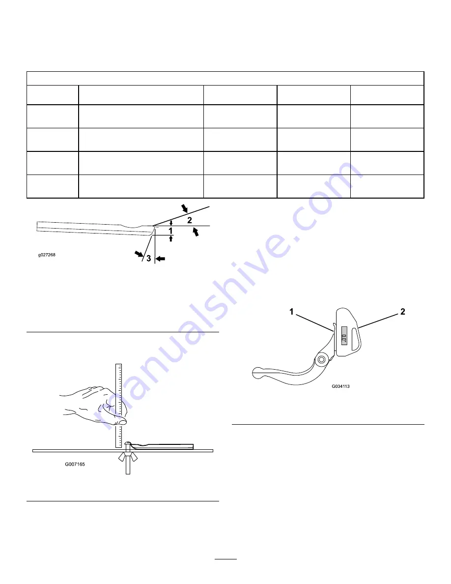
The bedknife service limits are listed in the following chart.
Important:
Operating the cutting unit with the bedknife below the service limit may result in poor
after-cut appearance and reduce the structural integrity of the bedknife for impacts.
Bedknife Service Limit Chart (Production Bedknife)
Bedknife
Part No.
Bedknife Lip Height
Service Limit*
Top/Front Grind
Angles
120-1641 (27 inch)
Low HOC
120-1642 (32 inch)
5.6 mm (0.220 inch)
4.8 mm (0.190 inch)
10/5°
112-8910 (27 inch)
EdgeMax®
112-8956 (32 inch)
6.9 mm (0.270 inch)
4.8 mm (0.190 inch)
10/5°
114-9388 (Model 03188/89/90, 27 inch)
Standard
114-9389 (Model 03191, 32 inch)
6.9 mm (0.270 inch)
4.8 mm (0.190 inch)
10/5°
114-9390 (Model 03192, 27 inch)
Heavy Duty
114-9391 (32 inch)
9.3 mm (0.370 inch)
4.8 mm (0.190 inch)
10/5°
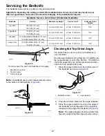
g027268
Figure 28
Recommended Top and Front Bedknife Grind Angles
1.
Bedknife service limit*
2.
Top grind angle
3.
Front grind angle
Note:
All bedknife service limit measurements relate
to the bottom of the bedknife (
g007165
Figure 29
Checking the Top Grind Angle
The angle that you use to grind your bedknives is
very important.
Use the angle indicator (Toro Part No. 131-6828) and
the angle-indicator mount (Toro Part No. 131-6829) to
check the angle that your grinder produces and then
correct for any grinder inaccuracy.
1.
Place the angle indicator on the bottom side of
the bedknife as shown in
g034113
Figure 30
1.
Bedknife (vertical)
2.
Angle indicator
2.
Press the Alt Zero button on the angle indicator.
3.
Place the angle-indicator mount on the edge of
the bedknife so that the edge of the magnet is
mated with the edge of the bedknife (
).
Note:
The digital display should be visible from
the same side during this step as it was in step
20


