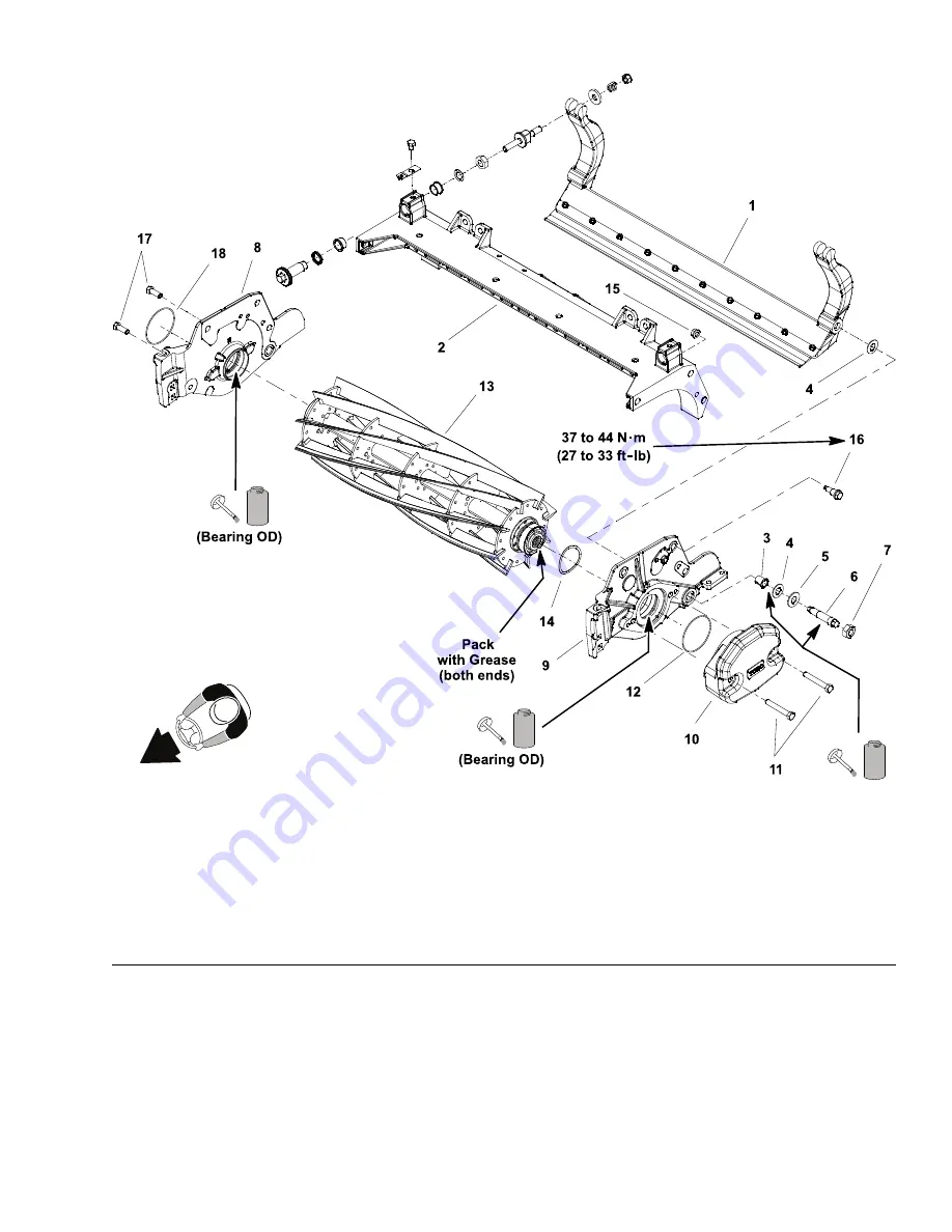
Reel Assembly
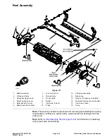
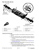
g343551
Figure 177
1.
Bedbar assembly
7.
Lock nut (2 each)
13.
Cutting reel assembly
2.
Cutting unit frame
8.
RH side plate
14.
Wire spring
3.
Flange bushing (2 each)
9.
LH side plate
15.
Flange nut (3 each per side plate)
4.
Plastic washer (4 each)
10.
Weight
16.
Shoulder bolt (3 each per side plate)
5.
Metal washer (2 each)
11.
Cap screw (2 each)
17.
Cap screw (2 each)
6.
Bedbar pivot bolt (2 each)
12.
O-ring
18.
O-ring
Note:
This section provides the procedure for removing and installing the cutting
reel assembly (cutting reel, spline inserts, grease seals and bearings) from the
cutting unit.
Note:
Refer to
Reel Assembly Service (page 8–26)
for information on replacing
cutting reel seals and bearings.
Reelmaster
®
3100-D/3105-D
Page 8–19
DPA Cutting Units: Service and Repairs
20252SL Rev A
Summary of Contents for 03200 Reelmaster 3100-D
Page 4: ...NOTES NOTES Page 4 Reelmaster 3100 D 3105 D 20252SL Rev A ...
Page 6: ...g341979 Figure 1 Preface Page 6 Reelmaster 3100 D 3105 D 20252SL Rev A ...
Page 10: ...Preface Page 10 Reelmaster 3100 D 3105 D 20252SL Rev A ...
Page 20: ...Safety Safety and Instructional Decals Page 1 10 Reelmaster 3100 D 3105 D 20252SL Rev A ...
Page 44: ...Specifications and Maintenance Special Tools Page 2 24 Reelmaster 3100 D 3105 D 20252SL Rev A ...
Page 224: ...Hydraulic System Service and Repairs Page 5 148 Reelmaster 3100 D 3105 D 20252SL Rev A ...
Page 385: ......


