Rotary Cartridge Valves (continued)
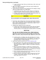
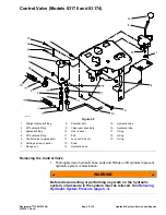
C. Loosen two (2) set screws that secure handle base to flow control valve
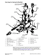
and remove base.
2. Make sure manifold is clean before removing the rotary cartridge valve.
Remove the valve and seal kit.
3. Visually inspect the manifold port and cartridge valve for damage to sealing
surfaces, damaged threads, and contamination.
A. Contamination may cause valves to stick or hang up, it can become
lodged in small valve orifices or seal areas causing valve malfunction.
B. If sealing surfaces appear pitted or damaged, the hydraulic system may
be overheating or there may be water in the system.
CAUTION
Use eye protection such as goggles when using compressed air.
4. If necessary, clean cartridge valve using clean mineral spirits. Submerge
valve in clean mineral spirits to flush out contamination. Particles as fine as
talcum powder can affect the operation of high pressure hydraulic valves.
Clean and dry with compressed air.
5. Reinstall rotary cartridge valve into manifold port:
A. Lubricate new O-rings and backup rings of seal kit with clean hydraulic
fluid and install. The O-rings and backup rings of seal kit must be
arranged properly on the cartridge valve for proper operation and sealing.
IMPORTANT
Use care when installing cartridge valves. Slight bending or
distortion of the stem tube can cause binding and malfunction.
Make sure that the deep well socket fully engages the valve base.
B. Lubricate threads on cartridge valve with clean hydraulic oil. Thread
rotary cartridge valve carefully into the manifold port. The valve should
go in easily without binding. Torque valve with deep well socket to
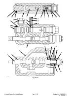
specification shown in manifold illustration.
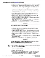
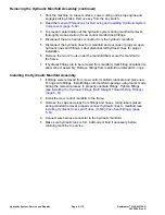
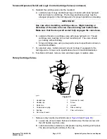
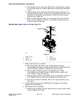
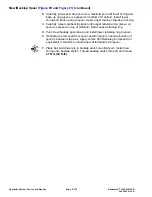
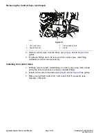
6. Install rotary handle (manifold shown in
and
A. Place handle base on flow control valve and position alignment mark on
base with number 1 on manifold. Secure base with two (2) set screws.
Apply a light coating of grease to chamfer on top of base to ease seal
installation.
B. Make sure that sleeve bearing is in handle cap. If necessary, press
sleeve bearing into cap. Install lip seal on cap with seal lip facing down.
C. Place bushing onto cartridge valve stem. Use a small amount of grease
to keep bushing toward the top of the valve stem.
D. Place compression spring and detent pin into handle cap. Use a small
amount of grease to hold detent pin in place.
E. Make sure that flow control valve is closed by rotating valve stem fully
clockwise. During handle installation, DO NOT rotate valve stem or
speed adjustment will be incorrect.
Hydraulic System: Service and Repairs
Page 5–116
Reelmaster
®
3100-D/3105-D
20252SL Rev A
Summary of Contents for 03200 Reelmaster 3100-D
Page 4: ...NOTES NOTES Page 4 Reelmaster 3100 D 3105 D 20252SL Rev A ...
Page 6: ...g341979 Figure 1 Preface Page 6 Reelmaster 3100 D 3105 D 20252SL Rev A ...
Page 10: ...Preface Page 10 Reelmaster 3100 D 3105 D 20252SL Rev A ...
Page 20: ...Safety Safety and Instructional Decals Page 1 10 Reelmaster 3100 D 3105 D 20252SL Rev A ...
Page 44: ...Specifications and Maintenance Special Tools Page 2 24 Reelmaster 3100 D 3105 D 20252SL Rev A ...
Page 224: ...Hydraulic System Service and Repairs Page 5 148 Reelmaster 3100 D 3105 D 20252SL Rev A ...
Page 385: ......

