Assembling the Drive System (continued)
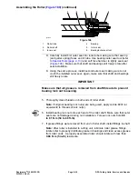
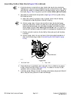
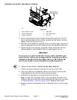
A. The outer faces of the drive and driven pulleys (not the idler pulley)
should be in-line within 0.76 mm (0.030 in).
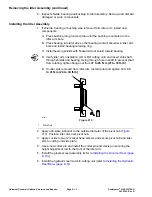
g214811
Figure 203
1.
Flange nut
3.
Flat washer
2.
Driven pulley
4.
Roller brush shaft
B. If necessary to align pulleys, remove driven pulley from brush shaft and
add or remove flat washer( s) until drive and driven pulleys are correctly
aligned (
).
C. If driven pulley was removed from roller brush shaft, apply anti-seize
lubricant to splines of pulley bore and slide pulley onto shaft. Install and
tighten flange nut until pulley is seated onto shaft and then torque flange
nut from
37 to 44 N·m (27 to 33 ft-lb)
. Use a ½ wrench on roller brush
shaft flats to prevent shaft from rotating when tightening nut.
IMPORTANT
The roller brush shaft must nor contact the cutting unit side plate.
Also, heavy brush contact on the rear roller will cause premature
brush wear.
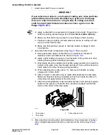
4. Check that brush is parallel to rear roller with 1.5 mm (0.060 in)clearance to
light contact with rear roller. If contact is incorrect, brush operation will be
adversely affected.
5. Install cover (item 20).There should not be a set screw installed in the bottom
of the cover.
6. Lubricate grease fittings on brush housings until grease purges past inboard
seals. Wipe excess grease from seals and fittings.
DPA Cutting Units: Service and Repairs
Page 8–46
Reelmaster
®
3100-D/3105-D
20252SL Rev A
Summary of Contents for 03200 Reelmaster 3100-D
Page 4: ...NOTES NOTES Page 4 Reelmaster 3100 D 3105 D 20252SL Rev A ...
Page 6: ...g341979 Figure 1 Preface Page 6 Reelmaster 3100 D 3105 D 20252SL Rev A ...
Page 10: ...Preface Page 10 Reelmaster 3100 D 3105 D 20252SL Rev A ...
Page 20: ...Safety Safety and Instructional Decals Page 1 10 Reelmaster 3100 D 3105 D 20252SL Rev A ...
Page 44: ...Specifications and Maintenance Special Tools Page 2 24 Reelmaster 3100 D 3105 D 20252SL Rev A ...
Page 224: ...Hydraulic System Service and Repairs Page 5 148 Reelmaster 3100 D 3105 D 20252SL Rev A ...
Page 385: ......

