B.
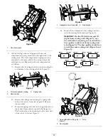
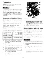
Insert the lift arm yoke onto the carrier frame
shaft (Figure 11).
C.
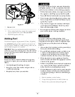
Insert the lift arm shaft into the lift arm and secure
it with the washer and lynch pin (Figure 12).
10.
Insert the cap over the carrier frame shaft and lift arm
yoke.
11.
Secure the cap and the carrier frame shaft to the lift
arm yoke with the snapper pin. Use the slot if a steering
cutting unit is desired or use the hole if the cutting unit
is to be locked in position (Figure 10).
12.
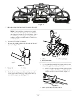
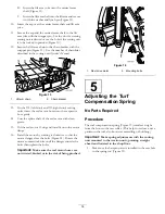
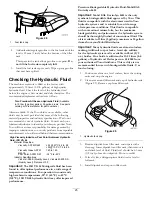
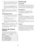
Secure the lift arm chain to the chain bracket with the
snapper pin (Figure 13). Use the number of chain links
described in the cutting unit
Operator's Manual
.
Figure 13
1.
Lift arm chain
2.
Chain bracket
13.
On the #4 (left front) and #5 (right front) cutting
units, insert the reel motor hoses into the respective
hose guide.
14.
Coat the spline shaft of the reel motor with clean
grease.
15.
Oil the reel motor O-ring and install it onto the motor
flange.
16.
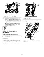
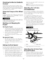
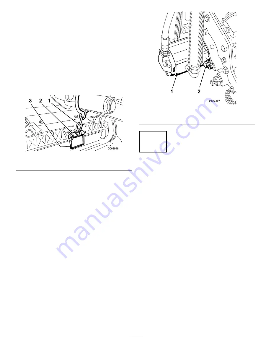
Install the motor by rotating it clockwise so that the
motor flanges clear the bolts (Figure 14). Rotate the
motor counterclockwise until the flanges encircle the
bolts then tighten the bolts.
Important:
Make sure the reel motor hoses are
not twisted, kinked or in the risk of being pinched.
Figure 14
1.
Reel drive motor
2.
Mounting bolts
5
Adjusting the Turf
Compensation Spring
No Parts Required
Procedure
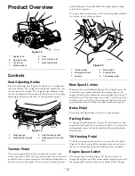
The turf compensation spring (Figure 15) transfers weight
from the front to the rear roller. (This helps to reduce a wave
pattern in the turf, also known as marcelling or bobbing.)
Important:
Make spring adjustments with the cutting
unit mounted to the traction unit, pointing straight
ahead and lowered to the shop floor.
1.
Make sure the hairpin cotter is installed in the rear hole
in the spring rod (Figure 15).
14
Summary of Contents for 03673
Page 46: ...Notes 46 ...
Page 47: ...Notes 47 ...


