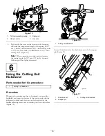
increments. By holding the switch down the engine will
automatically move to High or Low idle, depending on which
end of the switch is depressed.
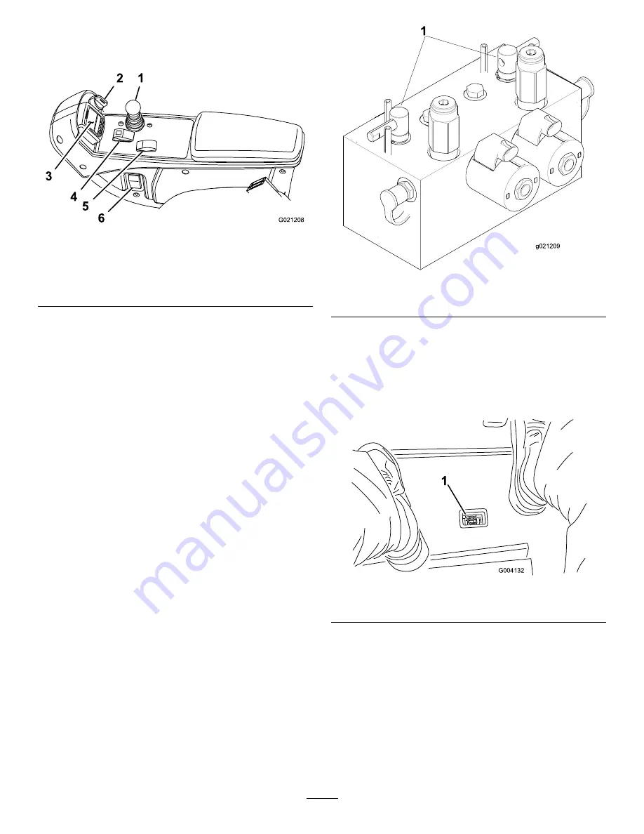
1
2
3
4
5
6
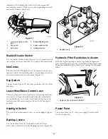
G021208
Figure 21
1.
Lower mow/raise control
lever
4.
Enable/disable switch
2.
Key switch
5.
Engine speed switch
3.
InfoCenter
6.
Headlight switch
Enable/Disable Switch
Use the enable/disable switch (Figure 21) in conjunction with
the lower mow/raise control lever to operate the cutter heads.
InfoCenter
The InfoCenter LCD display shows information about your
machine such as the operating status, various diagnostics and
other information about the machine (Figure 21).
Key Switch
The key switch (Figure 21) has three positions: Off, On/Run,
and Start.
Lower Mow/Raise Control Lever
This lever (Figure 21) raises and lowers the cutting units and
also starts and stops the cutterheads when the cutterheads
are enabled in the mow mode. The cutter heads cannot be
lowered when the mow/transport lever is in the transport
position.
Headlight Switch
Pivot the switch downward to turn on the headlights (Figure
21).
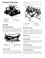
Backlap Levers
Use the backlap levers in conjunction with the lower
mow/raise control lever for backlapping the reels (Figure 22).
1
g021209
Figure 22
1.
Backlap levers
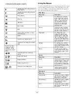
Hydraulic Filter Restriction Indicator
With the engine running at normal operating temperature,
view the indicator (Figure 23), it should be in the Green zone.
When the indicator is in the Red zone, change the hydraulic
filters.
Figure 23
1.
Hydraulic filter restriction indicator
Power Point
The power point is a 12 volt power supply for electronic
devices (Figure 24).
17
Summary of Contents for 03673
Page 46: ...Notes 46 ...
Page 47: ...Notes 47 ...

