background image

10

1

2

Figure 14

Cutting Unit Float Position

1.

Lockout pin

2.

Jam nut

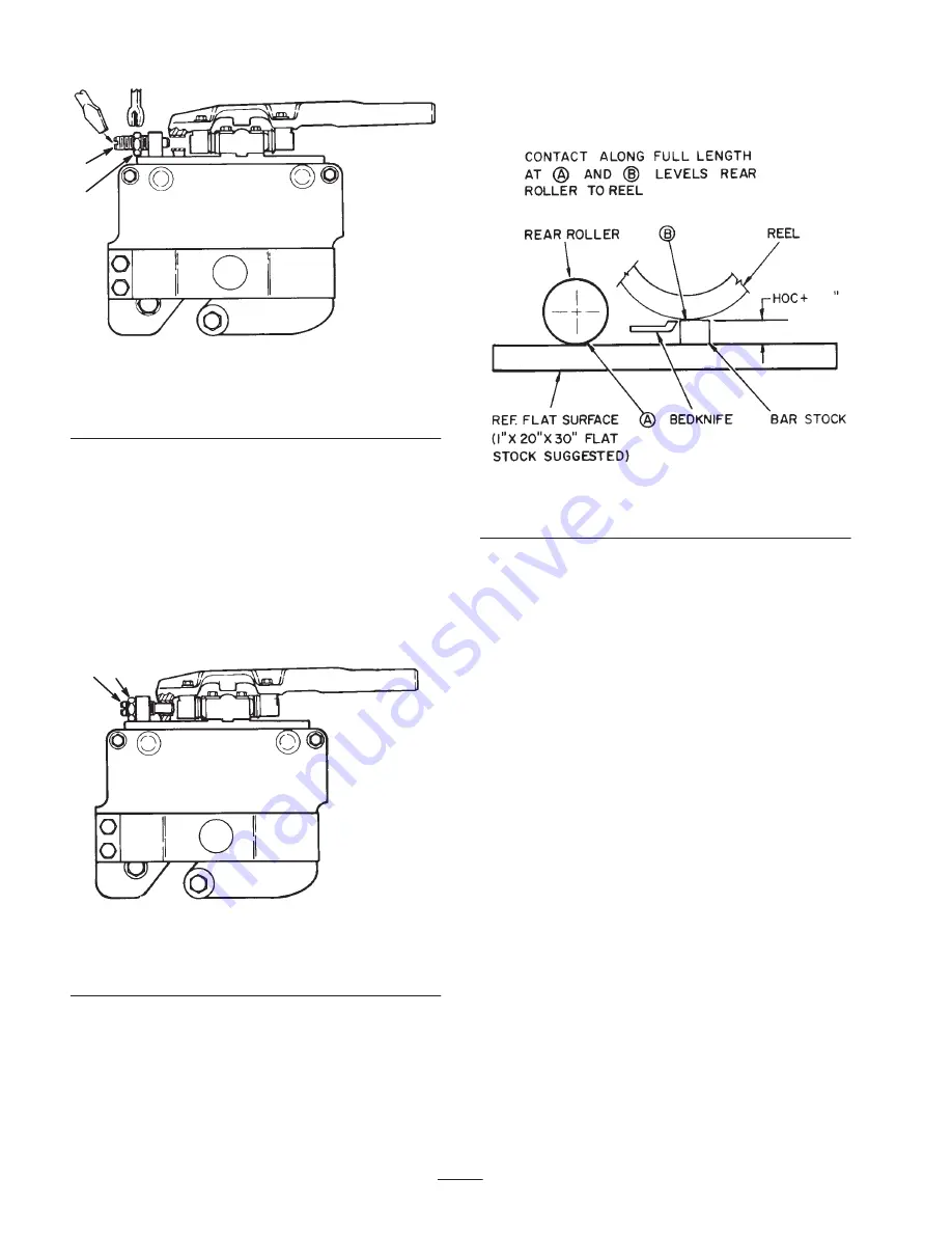
2. Insert a piece of bar stock 25–28 in. (70 cm) long

(Fig. 16), and approximately 3/8 in. (9.5 mm) thicker
than the desired height-of-cut, under the reel and up
against the bedknife cutting edge (Fig. 16). The reel
(not bedknife) must contact the bar stock along its full
length.

Note: Using a bar 3/8 in. (9.5 mm) thicker than
height-of-cut provides proper bedknife attitude (heeled
“up” in back) required for excellent low height-of-cut
performance.

1

2

Figure 15

Cutting Unit Fixed Position

1.

Lockout pin

2.

Jam nut

3. Loosen rear roller jam nuts and adjusting knobs and

push roller down against flat surface. At this point the
reel should be contacting the bar stock and the rear
roller contacting the flat surface. Contact should exist
along the entire length of the reel and rear roller.
Tighten rear roller adjustment knobs and jam nuts.
Recheck to be sure roller and reel are both still making

contact after the jam nuts have been tightened. Check
roller contact by trying to slide paper between the
roller and the flat surface.

3/8

Figure 16

Leveling the Rear Roller to the Reel

4. Rear roller is now leveled to the reel.

Adjusting the Final Height-of-Cut Using
the Gauge Bar

1. Raise cutting units and lock in the transport position.

Shut off the engine and remove the key.

2. Use gauge bar (Toro Part No. 98-1852) to set final

height-of-cut by adjusting front roller only.

Note: Position long cone nut (Fig. 17) on bottom for
heights of 1-1/4 in. or higher. Position short cone nut on
bottom for heights of below 1-1/4 in.

Summary of Contents for 03723

Page 1: ...0 5 7 and 11 Blade Cutting Units Reelmaster 4000 D Series Model No 03752 230000001 and Up Model No 03753 230000001 and Up Model No 03723 230000001 and Up Model No 03724 230000001 and Up Model No 03725 230000001 and Up Model No 03726 230000001 and Up ...

Page 2: ...w to operate and maintain your product properly The information in this manual can help you and others avoid injury and product damage Although Toro designs and produces safe products you are responsible for operating the product properly and safely Whenever you need service genuine Toro parts or additional information contact an Authorized Service Dealer or Toro Customer Service and have the mode...

Page 3: ...glementhazard stay away from moving parts Specifications General Specifications Height of cut 5 Blade 1 to 3 in 25 to 76 mm 7 Blade 1 2 to 1 3 4 in 9 5 to 45 mm 11 Blade 3 8 to 3 4 in 9 5 to 19 mm Height of cut adjustment Quick adjustment and positive locking is provided by locking type cone nuts Gauge marks of 1 4 in 6 3 mm are provided as a reference for easy changes of height of cut Clip variab...

Page 4: ...on the cutting unit Assembly Note Determine the left and right sides of the machine from the normal operating position Loose Parts Note Use this chart as a checklist to ensure that all parts have been received Without these parts total setup cannot be completed Description Qty Use Decals 2 Affix to cutting unit for CE Operator s manual 1 Read before operating Parts catalog 1 Registration card 1 Fi...

Page 5: ...d 3 cutting units remove 4 cover capscrews located at the outside end of the cutting unit drive housing Discard cover screws Mount a tipper plate to front left hand 2 cutting unit and the front right hand 3 cutting unit using flathead socket screws and locknuts supplied with tipper plates Fig 2 1 2 3 Figure 2 1 Inboard cutting unit cover 2 Tipper plate 3 Flathead socket capscrew Note Do not instal...

Page 6: ...uired amount of washers to pivot arm before installing fixed head assembly to lift arm Mount a Fixed Head Kit Assembly Fig 5 to each cutting unit with a cover plate attitude adjustment plate U bolts lockwashers and nuts supplied with kits Male end of floatation assembly to be positioned forward Tighten U bolts evenly 1 2 3 4 5 Figure 5 1 Fixed head assembly 2 Thrust washer as required 3 Cover plat...

Page 7: ...hers and capscrew as shown in Figure 7 1 2 3 4 Figure 7 1 Tipper bracket 2 Hose clamp 3 Spacer 4 Clamp plate 2 Mount tipper brackets to cutting units with capscrews and locknuts Important Raise and lower each cutting unit to ensure that there is no binding of hoses during operation 3 Tighten capscrews securing hose clamps to tipper brackets Mount the Roller Bumpers Floatation Kit Only Note Roller ...

Page 8: ...t washer on top bolt through the reel motor flange holes Thread the locknuts onto the bolts Rotate reel motor upward in the slotted hole in the housing to tension the drive belt and tighten the fasteners Fig 12 to approx 25 ft lb 34 N m Note Proper belt tension is achieved when belt deflects approximately 1 8 in 3 mm at mid point when 7 lb of force is applied Fig 12 1 Figure 12 1 Reel motor fasten...

Page 9: ...e in the tightening clockwise direction 4 Tighten adjuster locking nuts when completed making adjustments Sharp edges on the cutting units can cut or pinch hands or fingers When adjusting the cutting units wear heavy gloves Use care when turning the reels by hand Caution Important Adjusted correctly the reel will cut paper approx 03 in thick across its entire length The cutting units will provide ...

Page 10: ... should be contacting the bar stock and the rear roller contacting the flat surface Contact should exist along the entire length of the reel and rear roller Tighten rear roller adjustment knobs and jam nuts Recheck to be sure roller and reel are both still making contact after the jam nuts have been tightened Check roller contact by trying to slide paper between the roller and the flat surface 3 8...

Page 11: ...ut Adjustment Using Gauge Bar Important When set properly the front and rear rollers will contact the gauge bar and the screw head will be snug over the bedknife cutting edge when checked at both ends of the reel 5 Loosen lockout pin so cutting unit can float freely Fig 14 Quick Method for Changing Height of Cut after Initial Setup of a Floating Cutting Unit If the reel to bedknife adjustment has ...

Page 12: ...e rollers Fig 21 3 1 2 4 Figure 21 1 First screw 2 Second screw 3 Gauge bar angle 4 Front roller 4 Adjust the second screw to contact the bedknife 5 Place an angle indicator on the gauge bar and record the gauge bar angle Fig 21 6 Bedknife Angle step 1 Gauge Bar Angle step 5 Cutting Unit Attitude degrees 7 For adjusting the cutting unit attitude adjust the second screw for the desired attitude the...

Page 13: ...o it is 1 8 1 4 in 3 6 mm or higher above the level surface Allow greater clearance at the higher height of cut settings 4 Proper adjustment is achieved when the cutting unit does not scalp the grass in normal mowing conditions and yet is set high enough not to mar the turf and create undue wear on the skids or rollers Note Skids are used only with the cutting unit in the fixed position Front roll...

Page 14: ...t the engine and run at minimum throttle Lower either The center 3 cutting units 1 2 3 or Left hand 4 cutting unit or Right hand 5 cutting unit The center 3 cutting units run and shut off together With the 4 5 cutting units up and latched automatically shut off and the 1 2 3 cutting units down backlap the center 1 cutting unit from the rear of the machine with the long handled brush Backlap the 2 ...

Page 15: ...er should be cleanly sheared across the entire width of the reel If the paper is not sheared acceptably continue backlapping 8 After backlapping the 1 2 and 3 cutting units raise and latch these units and proceed with the 4 and 5 cutting units Note See the Toro Sharpening Manual Part No 80 300 for additional backlapping sharpening information Servicing the Bedknife Bedbar Note The bedbar on each c...

Page 16: ...dknife will be flat against the bedbar 4 Install the bedbar bedknife assembly to the cutting unit 1 2 3 Figure 27 1 Torque wrench 2 Tool Toro Part No 51 0880 3 Torque from center out Servicing the Reel Assembly Removing the Reel Assembly 1 Remove the guards from each end of the cutting unit and the front and rear roller assemblies Fig 28 1 2 3 4 1 Figure 28 1 Guard 2 Mountingfasteners 3 Bedbar mou...

Page 17: ...ve housing 5 Adjusting handle assembly 6 Woodruff key 7 Drive housing fasteners 7 Using a puller remove the driven pulley from the reel shaft Fig 31 Remove the woodruff key from the reel shaft 8 Remove the adjustment assembly and cone nut Belleville washer and shoulder bolt securing the housing to the sideplate Fig 31 Remove the housing 9 Slide the reel assembly out of the slots in the sideplates ...

Page 18: ...bolt Tighten the cone nut to 45 55 ft lb 8 Align the drive pin on the reel shaft with the notch in the bearing inner race and slide the bearing housing over the opposite end of the reel shaft Insert the shoulder bolt and Belleville washer through the rear bearing housing mounting hole Slide the bolt through the sideplate mounting hole Install the cone onto the bolt Tighten the cone nut to 45 55 ft...

Page 19: ...y sliding it off the shaft at both ends Fig 34 Installing the Roller Important When assembling a new roller to the cutting unit mount the roller so that the roller shaft locknut is on the right side of the cutting unit Fig 34 as viewed by the operator sitting on the seat of the machine This prevents the locknut from loosening during operation ...

Page 20: ... contamination use of unapproved coolants lubricants additives or chemicals etc Normal wear and tear items Normal wear and tear includes but is not limited to damage to seats due to wear or abrasion worn painted surfaces scratched decals or win dows etc Parts Parts scheduled for replacement as required maintenance are warranted for the period of time up to the scheduled replacement time for that p...

Reviews: