7
3. Stop the traction unit and remove the key. Manually
pull the lift arms, one at a time, to floor level. Repeat
this procedure for the #4 and #5 cutting units.
Without the cutting units installed, restarting the
engine will result in the lift arms raising.
Caution
4. Roll the appropriate cutting unit to lift arm and match
the male end of pivot arm with hole in lift arm.
Note: It may be necessary to spread slotted block on lift
arm slightly to slide pivot arm fully into hole.
5. Reinstall 3 lift arm bolts but do not tighten (Fig. 5).
Mounting the #4 and #5 Tipper
Brackets
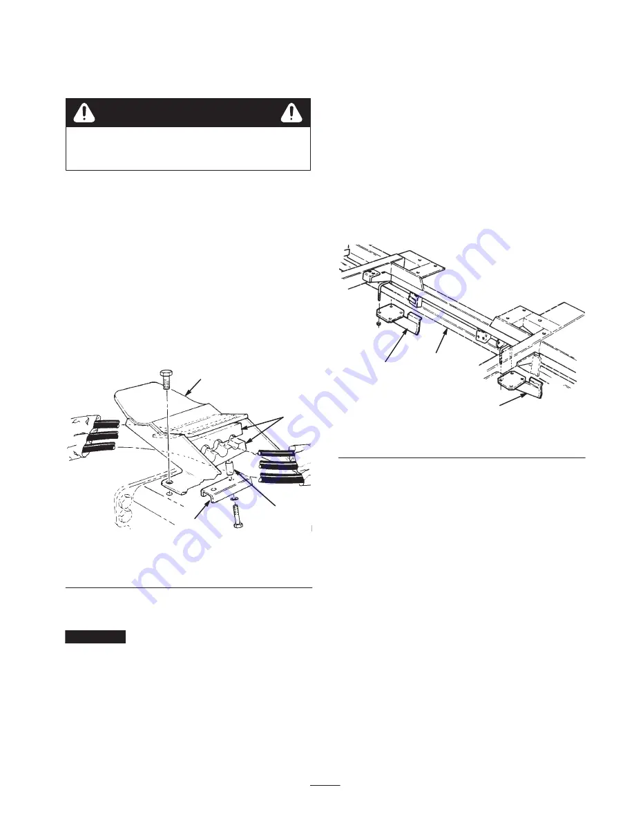
1. Loosely secure the hydraulic hoses to the underside of
each tipper bracket with hose clamps, spacers, clamp
plate, lock washers, and capscrew as shown in
Figure 7.
1
2
3
4
Figure 7
1.
Tipper bracket
2.
Hose clamp
3.
Spacer
4.
Clamp plate
2. Mount tipper brackets to cutting units with capscrews
and locknuts.
Important
Raise and lower each cutting unit to ensure
that there is no binding of hoses during operation.
3. Tighten capscrews securing hose clamps to tipper
brackets.
Mount the Roller Bumpers
(Floatation Kit Only)
Note: Roller bumpers are required only when operating
cutting units in the float position and front rollers are
installed.
1. Locate mounting position of roller bumpers (Fig. 8) on
each side of frame tube in front of #1 cutting unit.
2. Loosely secure a roller bumper to each side of frame
tube, as shown in Figure 8, with U-bolts and locknuts.
3. Align the center of each bumper with the respective
end of the roller on the #1 cutting unit and tighten the
locknuts.
1
2
1
Figure 8
1.
Roller bumpers
2.
Frame tube


