1
Inspection
Parts needed for this procedure:
1
Cutting unit
Procedure
After the cutting unit is removed from the box, inspect
the following:
1. Check each end of the reel for grease. Grease should
be visibly evident in the reel bearings and internal
splines of the reel shaft.
2. Ensure that all nuts and bolts are securely tightened.
3. Make sure the carrier frame suspension operates
freely and does not bind when moved back and forth.
2
Removing the Tipper
Assemblies
No Parts Required
Procedure
The tipper assemblies must be removed from the #1, #2
and #3 lift arms to avoid interference with the cutting
unit carrier frames.
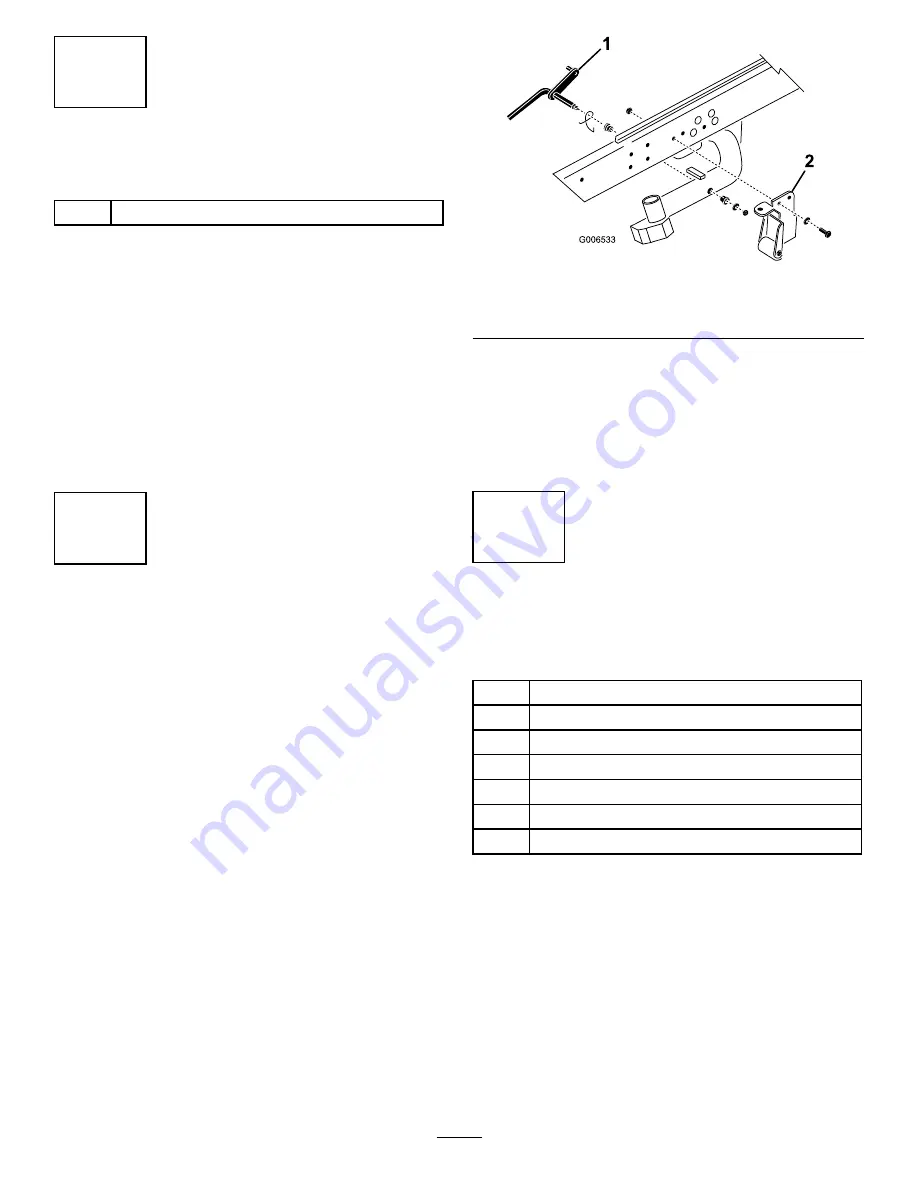
1. Remove the lock nut and washer securing the pivot
rod to the #2 lift arm (Figure 3). Remove the
pivot rod and spring from the lift arm. Repeat the
procedure on the #1 and #3 lift arms.
Figure 3
1.
Pivot rod
2.
Tipper support bracket
w/roller
Note:
The tipper bracket w/roller and the tipper
support brackets are not required when operating
the DPA cutting units (Figure 3). They may be
removed if desired.
2. Disconnect the lift chains from the cutting units, if
attached.
3
Mount the Lift Brackets and
Chains
Parts needed for this procedure:
5/7
Lift chain
5/7
Chain bracket
5/7
U-bolt
10/14
Nut
5/7
Screw
5/7
Washer
5/7
Nut
Procedure
Mount a chain bracket to each lift arm with a U-bolt and
2 nuts. Position the brackets as follows:
Note:
Refer to Figure 10 to determine the lift arm
number being described.
1. On lift arms #1, #4 and #5, position the chain
brackets and U-bolts 15 inches behind the center
line of the pivot knuckle (Figure 4). On lift arms #1
and #5 the brackets should be rotated to the right
10 degrees from vertical (Figure 4). On lift arm #4
5


